Sign In
Upload
Manuals
Brands
JCM Manuals
Cash Register
WBA-2x-SS2 Series
JCM WBA-2x-SS2 Series Manuals
Manuals and User Guides for JCM WBA-2x-SS2 Series. We have
1
JCM WBA-2x-SS2 Series manual available for free PDF download: Operation And Maintenance Manual
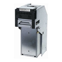
JCM WBA-2x-SS2 Series Operation And Maintenance Manual (92 pages)
World Bill Acceptor
Brand:
JCM
| Category:
Cash Register
| Size: 8.19 MB
Table of Contents
Table of Contents
3
JCM Part No. 960-000076R_Rev
10
1 General Information
13
Model Number Specifications
14
Precautions
14
User Cautions
14
Figure 1-2 Precautionary Symbols
14
Table 1-1 Model Number Specifications
14
Component Names
15
Figure 1-3 World Bill Acceptor (WBA) Major Component Parts
15
Specifications
16
Technical Specifications
16
Environmental Specifications
16
Electrical Specifications
16
Structural Specifications
16
Table 1-2 WBA-1X-Ssx Technical Specification
16
Table 1-3 WBA-1X Environmental Specification
16
Table 1-4 WBA-1X Electrical Specification
16
Table 1-5 WBA-1X Structural Specification
16
System Configuration
17
Primary Features
17
Figure 1-4 WBA System Configuration
17
Figure 1-5 WBA Bill Guide Interchangeability
17
Figure 1-6 WBA Easy Bill Retrieval Feature
17
Standard Unit Dimensions
18
Figure 1-7 Bill Acceptor WBA-1X-SS Complete Unit Dimensions Diagram
18
Country Codes
19
Table 1-6 Country Code Listings
19
2 Installation/Operation
21
Installation
21
Changing Bill Guides
21
Figure 2-1 Right Side Panel Dip Switch Block
21
Figure 2-2 Side Mounting Screw Hole Locations
21
Input/Output Circuits
22
Figure 2-3 Removing Old Bill Guides
22
Figure 2-4 Installing New Bill Guides
22
Figure 2-5 WBA 12, 13, 22 & 23 Input/Output Circuit Diagram
22
Figure 2-6 WBA 10, 11, 20 & 21 Input/Output Circuit Diagram
22
Connector Pin Assignments
23
Table 2-1 Connector CN1 Pin Assignments
23
Table 2-2 Connector CN2 Pin Assignments
23
Table 2-3 Relay Connector Pin Assignments
23
Table 2-4 WBA-10/11,20&21-SS 12 Pin Rear Panel Connector Pin
23
Table 2-5 WBA-12/13,22&23-SS2 20 Pin Rear Panel Connector Pin
24
Cable Interconnection
25
Figure 2-7 Typical WBA 1X/2X SS Cabling Requirements
25
Figure 2-8 Typical WBA 1X/2X SS2 Cabling Requirements
25
DIP Switch Configurations
26
WBA-1X and WBA-2X Head Sensor Lens Differences
26
Figure 2-9 WBA 1X-SS & 2X-SS Acceptor Head Lens Differences
26
Table 2-6 DIP Switch Settings
26
Retrieving Bills
27
Clearing a Bill Jam
27
Figure 2-10 Removing the WBA Cash Box
27
Figure 2-11 Retrieving Bills
27
Figure 2-12 Clearing an Entrance Bill Jam
27
Figure 2-13 Clearing a Transport Unit Bill Jam
27
Cleaning/Preventive Maintenance
28
Available Cleaning Card
28
Card Features
28
Directions for Use
28
Figure 2-14 Clearing a Cash Box Inlet Bill Jam
28
Figure 2-15 Cleaning the WBA Bill Path
28
Figure 2-16 JCM Waffletechnology Cleaning Card
28
ID-003 Standard Interface Operational Flowchart
29
Figure 2-17 WBA Bill Acceptor Operational Flowchart
29
3 Communications
31
4 Disassembly/Reassembly
33
Tool Requirements
33
Primary Unit Disassembly
33
Figure 4-1 WBA Acceptor Head Removal
33
Figure 4-2 WBA Transport Unit Removal
33
Figure 4-3 WBA Unit Cash Box Removal
33
Acceptor Unit Disassembly
34
Upper Sensor Circuit Board Removal
34
Lower Sensor Circuit Board Removal
34
Figure 4-4 WBA Acceptor's Upper Sensor Board Cover Removal
34
Figure 4-5 WBA Acceptor's Upper Sensor Board Removal
34
Figure 4-6 WBA Acceptor's Lower Sensor Board Cover Removal
34
Figure 4-7 WBA Acceptor's Lower Sensor Board Removal
34
Belt Tension Assembly Removal
35
Transport Unit Disassembly
35
Transport CPU Circuit Board Removal
35
Figure 4-8 Acceptor Head Drive Gear Removal
35
Figure 4-9 Acceptor Head Drive Belt Assembly Removal
35
Figure 4-10 Acceptor Head Drive Gear Tension Unit Disassembly
35
Figure 4-11 WBA 10/11 CPU Board Removal
35
Stacker Encoder Sensor Board Removal
36
Figure 4-12 WBA Transport CPU Board Assembly Removal
36
Figure 4-13 WBA 12/13 CPU Board Disconnect
36
Figure 4-15 Transport CPU Board Removal
36
Stacker Motor Removal
37
Transport Encoder Sensor Board Removal
37
Transport Drive Motor Removal
37
Entrance Lever Sensor Board Removal
37
Figure 4-16 Stack Encoder Sensor Board Removal
37
Figure 4-17 Transport Stack Motor Removal
37
Figure 4-18 Transport Encoder Sensor Board Removal
37
Figure 4-19 Transport Drive Motor Removal
37
Solenoid Lever Assembly Removal
38
Solenoid Lever Sensor Board Removal
38
Figure 4-20 Entrance Lever Sensor Board Removal
38
Figure 4-21 Transport Solenoid Cover Removal
38
Figure 4-22 Transport Solenoid Lever Sensor Board Removal
38
Figure 4-23 Transport Solenoid Lever Assembly Removal
38
Feed-Out Sensor Assembly Removal
39
Feed-Out Sensor Assembly Disassembly
39
Upper Timing Belt Removal
39
Home Position Sensor Board Removal
39
Figure 4-24 Complete Transport Solenoid Lever Assembly's Disassembly
39
Figure 4-25 Transport Feed-Out Sensor Assembly Removal
39
Figure 4-26 Transport Feed-Out Sensor Disassembly
39
Figure 4-27 Transport Upper Timing Belt Drive Gear Removal
39
Upper Timing Belt Removal Continuation
40
Lower Timing Belt Removal
40
Figure 4-28 Transport Home Sensor Board Removal
40
Figure 4-29 Transport Timing Belt Removal
40
Figure 4-30 Complete Transport Timing Belt Shaft Component Disassembly
40
Figure 4-31 Lower Timing Belt Access
40
Cash Box Disassembly
41
Pusher Mechanism Removal
41
Pusher Mechanism Cover Removal
41
Pusher Mechanism Timing Belt Removal
41
Figure 4-32 Lower Timing Belt Removal
41
Figure 4-33 Pusher Mechanism Removal
41
Figure 4-34 Pusher Mechanism Cover Removal
41
Figure 4-35 Coupling Bracket Handle Removal
41
Figure 4-36 Pusher Mechanism Gear Removal
42
Figure 4-37 Pusher Mechanism Belt Removal
42
5 Wiring Diagrams
43
WBA Primary Components Diagram
43
WBA-14-SS3B System Wiring Diagram
43
WBA-15-SS3B System Wiring Diagram
43
WBA-24-SS3B System Wiring Diagram
43
WBA-25-SS3B System Wiring Diagram
43
Figure 5-1 World Bill Acceptor (WBA) Primary Components
43
Figure 5-2 WBA-14-SS3B Bill Acceptor System Wiring Diagram
45
Figure 5-3 WBA-15-SS3B Bill Acceptor System Wiring Diagram
46
Figure 5-4 WBA-24-SS3B Bill Acceptor System Wiring Diagram
47
Figure 5-1 WBA-25-SS3B Bill Acceptor System Wiring Diagram
48
6 Calibration and Testing
49
Workbench Tool Requirements
49
Software Download Preparation
49
Figure 6-1 Required WBA Download Workbench Tools
49
Software Downloading Procedure
50
Program Installation
50
Calibration Procedure
50
Figure 6-2 WBA DIP Switch & Port Location
50
Figure 6-3 Initial Setup Screen
50
Figure 6-4 Head Installed Confirmation
50
Figure 6-5 White Paper Calibration Screen
50
Figure 6-6 White Calibration Paper Types
51
Figure 6-7 Inserting White Calibration Paper
51
Figure 6-8 White Calibration Occurring Screen
51
Figure 6-9 Black Paper Calibration Screen
51
Figure 6-10 Black Calibration Paper Types
51
Figure 6-11 Inserting Black Calibration Paper
51
Figure 6-12 Black Calibration Occurring Screen
51
Figure 6-13 White Re-Calibration Request Screen
52
Figure 6-14 Remove Calibration Paper Screen
52
Figure 6-15 Removing Final Calibration Paper
52
Figure 6-16 Paperless Calibration Screen
52
Figure 6-17 Magnetic Test Calibration Screen
52
Figure 6-18 Aligning the MAG Head Calibration Test Board
52
Figure 6-19 Magnetic Adjust Value Screen
53
Figure 6-20 Locating the MAG Head Calibration Peak Value Reading
53
Figure 6-21 Adjusting Magnetic Gain Screen
53
Figure 6-23 Writing Adjustment Data Screen
53
Figure 6-24 End Calibration Screen
53
Calibration Error Messages
54
Sensor Signal and Name Conversions
54
Flash Memory Download Procedure
54
When to Download
54
Figure 6-25 Typical Error Message Screen
54
Table 6-1 WBA-1X-SS Validator Sensor Names
54
Table 6-2 WBA-2X-SS Validator Sensor Names
54
7 Exploded Views and Parts Lists
55
Entire WBA Unit View and Parts
55
Figure 7-1 Entire WBA Unit Exploded View
55
Entire WBA Unit Parts List
56
Table 7-1 Entire WBA Unit Parts List
56
WBA 12/13 Acceptor Head Exploded Views
57
Figure 7-2 WBA 12/13 Acceptor Head Exploded View
57
WBA 22/23/24/25 Acceptor Head Exploded View
58
Figure 7-3 WBA 22/23/24/25 Acceptor Head Exploded View
58
Table 7-2 WBA 12/13&22/23/24/25 Acceptor Head Collective Parts List
59
WBA 12/13 & 22/23/24/25 Acceptor Head Collective Parts List
59
WBA Transport Unit Exploded Views (Continued)
61
Figure 7-5 WBA Transport Unit Exploded View (Part 2)
62
WBA Transport Unit Exploded Views (Continued)
62
Figure 7-6 WBA Transport Unit Exploded View (Part 3)
63
WBA Transport Unit Exploded Views (Continued)
63
Table 7-3 WBA Transport Unit Collective Parts List
65
WBA Frame Unit Exploded View
69
Figure 7-7 WBA Frame Unit Exploded View
69
Table 7-4 WBA Frame Unit Parts List
70
WBA Cash Box Unit Exploded View
71
Figure 7-8 WBA Cash Box Exploded View (Part 1)
71
Figure 7-9 WBA Cash Box Exploded View (Part 2)
72
WBA Cash Box Unit Exploded View (Continued)
72
Table 7-5 WBA Cash Box Collective Parts List
73
8 Index
75
A Troubleshooting
77
Introduction
77
Troubleshooting Overview
77
Fault Table Listings
77
Table A-1 General Fault Conditions
77
Table A-2 Adjustment Fault Conditions
79
Table A-3 Communication Fault Conditions
79
Performance Tests
80
Choosing and Selecting Operational Tests
80
Auto Calibration Mode
80
Calibration Error Table
80
Table A-4 WBA-1X Calibration Error Indications
80
Diagnostic Test Mode
81
Functional Tests
81
Head Sensor Test (PH06
81
Table A-5 WBA-1X/2X Functional Test DIP Switch Settings
81
Head Sensor Test DIP Switch Settings
82
Head Sensor Locations
82
Figure A-1 WBA 1X Head Sensor Locations
82
Table A-6 WBA-1X/2X Head Sensor Test DIP Switch Setting Chart
82
Transport Sensor Test (PH07
83
Transport Sensor Test
83
Figure A-2 WBA 2X Head Sensor Locations
83
Table A-7 WBA-1X/2X Transport Sensor Test DIP Switch Setting Chart
83
Transport Sensor Locations
84
Sensor, Circuit Board and Motor Locations
84
Figure A-3 WBA-1X/2X Transport Sensor Locations
84
Figure A-4 WBA-1X/2X Sensor, Circuit Board and Motor Location Diagram
84
Bill Acceptance Test
85
Bill Acceptance Test Modes
85
Bill Identification in Bill Acceptance
85
Forced Download Mode
85
Table A-8 WBA-1X/2X Bill Acceptance Test Setting Chart
85
Table A-9 WBA-1X/2X Forced Download Mode Chart
85
DT-104 Downloading
86
PC Downloading
86
Abnormal Error Code Table
87
Test Mode 4 Only Error Table
87
Table A-10 WBA-1X/2X Abnormal Operation Code Table
87
Table A-11 WBA-1X/2X Test Mode 4 Abnormal Operation Code Table
87
Return Code Error Table
88
Table A-12 WBA-1X/2X Return Error Code Table
88
B Glossary
89
Advertisement
Advertisement
Related Products
JCM WBA-2x-SS Series
JCM WBA Series
JCM WBA-1x-SS2 Series
JCM WBA-1x-SS Series
JCM WBA-SS Series
JCM WBA
JCM WBA-10
JCM WBA-11
JCM WBA-12
JCM WBA-13
JCM Categories
Bank Note Validator
Banknote Counter
Printer
Cash Register
Plumbing Product
More JCM Manuals
Login
Sign In
OR
Sign in with Facebook
Sign in with Google
Upload manual
Upload from disk
Upload from URL