Sign In
Upload
Manuals
Brands
J&E Hall Manuals
Air Compressor
HallScrew HSO 2035
J&E Hall HallScrew HSO 2035 Manuals
Manuals and User Guides for J&E Hall HallScrew HSO 2035. We have
1
J&E Hall HallScrew HSO 2035 manual available for free PDF download: Installation, Operation And Maintenance Manual
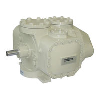
J&E Hall HallScrew HSO 2035 Installation, Operation And Maintenance Manual (94 pages)
Open Drive Single Screw Compressors
Brand:
J&E Hall
| Category:
Air Compressor
| Size: 1.33 MB
Table of Contents
Safety
3
Personnel Permitted to Install, Commission and Maintain the Plant
3
Mechanical
3
Examination of Pressure Systems
4
Noise Hazard
4
Electrical
4
Lubricating Oils
5
Ammonia Refrigerant 717
5
Hydrochlorofluorocarbon and Hydrofluorocarbon Refrigerants
6
Table of Contents
7
Contentslist of Figures
7
List of Figures
9
List of Tables
9
About this Publication
10
Safety Warnings and Symbols
10
Units of Measurement
10
Terminology
10
Ordering Extra Copies
10
Misuses that Invalidate Guarantee
11
Application
11
System Provisions
11
Prolonged Storage
12
Commissioning Provisions
12
General Description
13
Main Features
13
Construction
13
The Compression Process
14
The Compression Process
16
Suction
16
List of Figures Fig 1 Compression Process
16
Compression
17
Discharge
17
Capacity Control and Volume Ratio
18
Fig 2 Capacity Control Slide Valve in Operation
18
Slide Valve Actuation
19
Minimum Load Interlock
19
Capacity Control Solenoid Valve Arrangements
20
Capacity Control Arrangement Using Separate Pairs of Solenoid Valves
20
Compressor Loading
20
Compressor Unloading
20
Hold Slide Valve Position
20
Table 1 Capacity Control Solenoid Valve Options
20
Flow Control Valves
21
Fig 3 Capacity Control Arrangement Using Separate Pairs of Solenoid Valves
22
Capacity Control Arrangement Using a 4-Way Solenoid Valve
23
Compressor Loading
23
Compressor Unloading
23
Hold Slide Valve Position
23
Flow Control Valves
23
Fig 4 Capacity Control Arrangement Using a 4-Way Solenoid Valve
24
Capacity Control by Inverter Drive
25
Inverter Size
25
Inverter Set-Up
25
Linear Variable Displacement Transducer (LVDT)
26
HB Linear Variable Displacement Transducer (HBLVDT)
26
To 20 Ma Calibration - Compressor Stopped
26
To 20 Ma Calibration - Compressor Running
27
Fig 5 HBLVDT Arrangement and External Wiring Connections
27
Fig 6 HBLVDT External Wiring Connections for Explosion-Proof Version
28
Fitting a New HBLVDT Electronics Module
29
MSI Linear Variable Displacement Transducer (MSI LVDT)
30
Fig 7 MSI LVDT Arrangement and Wiring Connections
30
Fig 8 Signal Conditioning Module
31
Table 2 MSI LVDT/HBLVDT Part Number Cross-Reference
31
Compressor Lubrication, Sealing and Cooling
32
Capacity Control Actuation
32
Bearing Lubrication
32
Shaft Seal Lubrication, Sealing and Cooling
32
Oil Injection for Sealing and Cooling
32
Oil Support System
34
Oil Injection/Lubrication
34
Oil Drain
34
Oil Drain Sensor
34
Oil Separation
35
Oil Separator Design
35
Oil Separator Provisions
35
Oil Return
36
Suction/Discharge Non-Return Valve
36
Oil Heaters
36
Oil Low Level
36
Oil Balance Lines
36
Oil Circulation
37
Oil Differential Pressure Monitoring
37
Table 3 Pumping Capacities for Continuously Running Oil Pump
37
Oil Differential Pressure 1 (ODP1)
38
Table 4 Summary of Differential Pressure Sensing
38
Oil Flow Switch
39
Oil Differential Pressure 2 (ODP2)
39
Oil System Differential Pressure Drop
39
Maintaining Discharge Pressure at Start up
39
Oil Filter
40
Compressor Cooling
40
Fig 9 Maintaining Discharge Pressure at Start up
40
Lubricating Oils
41
Prolonged Storage
42
Placing the Compressor into Store
42
Taking the Compressor out of Storage
43
Installing the Compressor
44
Lifting the Compressor
44
Making Connections
44
Fig 10 Lifting the Compressor
44
Electrical Wiring Connections and Interlocks
45
Commissioning and Operation
46
Checks Prior to the First Start
46
General Checks
46
Compressor Drive Motor
47
Checking Compressor Rotation
47
Lubrication System
48
First Start
48
Normal Starting and Running
50
Adding Oil to the System
51
Running-In the Compressor
52
Filters and Strainers
52
Compressor Suction Strainer
52
Oil Filter
52
Refrigerant Filter/Drier
52
Monitoring for Moisture
52
Lubricating Oil
52
Checking for Leaks
53
Compressor Drive Motor Coupling
53
Compressor and Drive Motor Holding-Down Bolts
53
Pumping down and Opening up the Compressor
54
Preparing for Pump down
54
Pumping down the Compressor
54
Isolating the Electrical Supply
54
Removing the Residual Refrigerant Gas
55
Opening up the Compressor
55
Re-Instating the Compressor
55
Maintenance
57
Spare Parts
57
Filters and Strainers
57
Running-In
58
Maintenance Schedule
58
Maintenance Intervals
58
Daily
58
Table 5 Filter and Strainer Locations
58
Weekly
59
Monthly
59
Every Year, or at Intervals of 5,000 Operating Hours
60
Every 3 Years, or at Intervals of 15,000 Operating Hours
61
Every 6 Years, or at Intervals of 25,000 Operating Hours
61
Every 12 Years, or at Intervals of 50,000 Operating Hours
61
Every 24 Years, or at Intervals of 100,000 Operating Hours
62
Prolonged Shutdown
62
Maintenance Check List
62
Table 6 Maintenance Check List
63
Oil Acid Content Record
64
Table 7 Oil Acid Content Record - Plants Charged with Refrigerant Other than Ammonia (R717)
64
Appendix 1 Compressor Data
65
Appendix 2 Oil Support System Schematic Flow Diagrams
73
Fig 11 Key to Schematic Flow Diagrams
73
Fig 12 no Oil Pump
74
Fig 13 Start-Up Oil Pump: Common Oil Lines for Injection and Lubrication
75
Fig 14 Continuously Running or Demand Oil Pump: Common Oil Lines for Injection and Lubrication
76
Appendix 3 Limits of Operation Envelopes
77
Appendix 4 HS 2000 Series Compressor Replacement Parts
82
Appendix 5 Plant Performance Record
86
Appendix 6 Pepperl & Fuchs Signal Conditioning Module KFU8-USC-1.D Set-Up
88
Table 8 Basic Set up for 4 Ma and 20 Ma Output Values at Minimum and Maximum Slide Valve Positions
89
Table 9 Setting the Display to Read 0 at Minimum Load and 100 at Maximum Load
91
Table 10 Setting the Relay Switch Value
92
Advertisement
Advertisement
Related Products
J&E Hall HallScrew HSO 2000 Series
J&E Hall HallScrew HSO 2024
J&E Hall HallScrew HSO 2028
J&E Hall HallScrew HSO 2031
J&E Hall HBLT-A1-5
J&E Hall HBLT-A1-55U
J&E Hall HBLT-A1-85U
J&E Hall HBLT-A1B-30U
J&E Hall HBLT-A1-30U
J&E Hall HBLT-A1-22
J&E Hall Categories
Heat Pump
Accessories
Controller
Freezer
Transmitter
More J&E Hall Manuals
Login
Sign In
OR
Sign in with Facebook
Sign in with Google
Upload manual
Upload from disk
Upload from URL