Sign In
Upload
Manuals
Brands
Jäger Manuals
Industrial Equipment
Z80-H536.08 S8JRVW3
Jäger Z80-H536.08 S8JRVW3 Manuals
Manuals and User Guides for Jäger Z80-H536.08 S8JRVW3. We have
1
Jäger Z80-H536.08 S8JRVW3 manual available for free PDF download: Manual
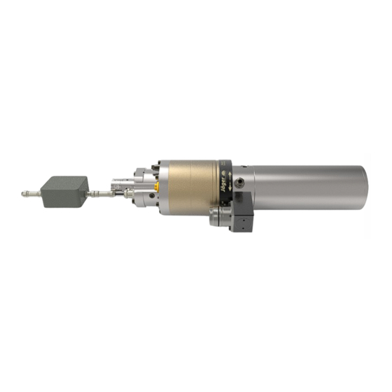
Jäger Z80-H536.08 S8JRVW3 Manual (52 pages)
High Frequency Spindle
Brand:
Jäger
| Category:
Industrial Equipment
| Size: 1.31 MB
Table of Contents
Table of Contents
3
Preliminary Information
5
Purpose of the Manual
5
Explanation of Symbols Used
5
Transport and Packaging
6
Scope of Supply of HF Spindle
6
Optional Accessories
6
Documentation Supplied
6
Packaging of HF Spindle
7
Designated Use
7
Permissible Types of Machining
7
Permissible Materials
7
Safety Instructions
8
Safe Working
9
Shutdown of HF Spindle
10
Installation and Maintenance
10
Modification and Repair
10
Improper Operation
10
Technical Description
11
Connections of HF Spindle
11
Electrical Connection
12
Cooling
12
Sealing Air
12
Taper Cleaning
12
Pneumatic Tool Change
12
Internal Coolant Supply
13
Cooling Lubricant
13
Filtering the Cooling Lubricant
14
Avoiding Pressure Peaks
14
Leakage
14
Internal Coolant Supply, Vertical Installation
15
Internal Coolant Supply, Horizontal Installation
15
Technical Specifications
16
Dimensions
17
Technical Data Sheet (KL7007 , AC-Motor)
18
Performance Diagram
19
Wiring Diagram
20
Motor Protection PTC 160°C
23
Tool Change Monitoring
23
Displacement Measuring System (Ott-Jakob)
24
Technical Specifications
24
Signals
25
Installation
25
Scaling
26
Speed and Position Sensor (Minicoder)
26
Technical Specifications
26
Eddy Current Sensor
27
Measurement Principle
27
Technical Specifications
27
Air-Borne Noise Emissions
28
Operating Location
29
Installation
30
Installing the HF Spindle
30
Diameter of Media Supply Line
31
Cooling Water
31
Quality of Cooling Water
31
Setting the Cooling
31
Compressed Air
32
Air Purity Classes (ISO 8573-1)
32
Setting the Sealing Air
32
Setting Values
33
Setting the Internal Coolant Supply
34
Sensor Electronics of Measuring System (Optional Accessory)
35
Wiring of Measuring System
35
Commissioning
36
Running-In Schedule
36
Daily Start-Up
37
Shutdown Signal
37
Commissioning after Storage
37
Tool Change
38
Clockwise and Counter-Clockwise
38
Pneumatic Taper Change
39
Automatic Hollow Shank Taper Tool Clamp
39
Tool Changing Station (Optional Accessory)
40
Pneumatic Taper Change
40
Installing the Changing Station
40
Maintenance
40
Workflow
41
Pneumatic Workflow
41
Electrical Workflow
42
Signals
42
Tools for High Speed Cutting
43
Maintenance
44
Ball Bearings
44
Daily Cleaning
44
Before Commencing Work
44
With Every Tool Change
45
Every Time the Clamping Device Is Changed
45
In the Case of Storage
45
Monthly Maintenance
45
Long Periods of Storage
45
Maximum Storage Time
45
Dismantling
46
Disposal and Environmental Protection
46
Service and Repairs
47
Service Partners
47
Malfunctions
48
Declaration of Incorporation
51
Advertisement
Advertisement
Related Products
Jäger S80-M450.34 S5
Jäger S80-K450.42 S5
Jäger S80-H450.01 S5
Jäger S80-M450.33 S3
Jäger S80-H450.01 S21
Jäger F140-H830.04 S11JRW3V
Jäger S62-M280.07 S5
Jäger S62-M360.05 S5
Jäger S62-M360.02 S3
Jäger SP33-M260.01 S26
Jäger Categories
Industrial Equipment
Control Systems
Controller
Data Loggers
Engine
More Jäger Manuals
Login
Sign In
OR
Sign in with Facebook
Sign in with Google
Upload manual
Upload from disk
Upload from URL