Sign In
Upload
Manuals
Brands
ITT Manuals
Water Pump
GOULDS PUMPS LF 3196 i-FRAME
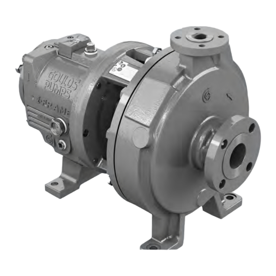
ITT GOULDS PUMPS LF 3196 i-FRAME Pump Manuals
Manuals and User Guides for ITT GOULDS PUMPS LF 3196 i-FRAME Pump. We have
1
ITT GOULDS PUMPS LF 3196 i-FRAME Pump manual available for free PDF download: Installation, Operation And Maintenance Manual
ITT GOULDS PUMPS LF 3196 i-FRAME Installation, Operation And Maintenance Manual (155 pages)
Brand:
ITT
| Category:
Water Pump
| Size: 13 MB
Table of Contents
Table of Contents
3
Introduction and Safety
7
Introduction
7
Requesting Other Information
7
Safety
7
Safety Terminology and Symbols
8
Environmental Safety
9
User Safety
9
Product Warranty
12
ATEX Considerations and Intended Use
12
Transportation and Storage
17
Inspect the Delivery
17
Inspect the Package
17
Inspect the Unit
17
Transportation Guidelines
17
Pump Handling
17
Lifting Methods
17
Storage Guidelines
20
Pump Storage Requirements
20
Frostproofing
21
Product Description
22
General Description LF 3196
22
Part Description LF 3196
23
General Description I-ALERT®2 Equipment Condition Monitor
24
Nameplate Information
25
Installation
29
Pre-Installation
29
Pump Location Guidelines
29
Foundation Requirements
30
Baseplate-Mounting Procedures
31
Prepare the Baseplate for Mounting
31
Install the Baseplate Using Shims or Wedges
31
Install the Baseplate Using Jackscrews
32
Install the Baseplate Using Spring Mounting
34
Install the Baseplate Using Stilt Mounting
35
Baseplate-Leveling Worksheet
37
Install the Pump, Driver, and Coupling
38
Pump-To-Driver Alignment
38
Alignment Checks
38
Permitted Indicator Values for Alignment Checks
39
Alignment Measurement Guidelines
39
Attach the Dial Indicators for Alignment
40
Pump-To-Driver Alignment Instructions
40
C-Face Adapter
43
Grout the Baseplate
44
Piping Checklists
45
General Piping Checklist
45
Suction-Piping Checklist
47
Discharge Piping Checklist
50
Commissioning, Startup, Operation, and Shutdown
52
Preparation for Startup
52
Remove the Coupling Guard
53
Check the Rotation
55
Impeller-Clearance Check
55
Impeller Clearances (LF 3196)
56
Impeller-Clearance Setting
56
Set the Impeller Clearance - Dial Indicator Method (All Except CV 3196, CV 3198, and LF 3196 Size 1X1.5-4)
57
Set the Impeller Clearance - Feeler Gauge Method (All Except CV 3196, CV3198 and LF 3196 Size 1X1.5-4)
58
Couple the Pump and Driver
59
Install the Coupling Guard
60
Bearing Lubrication
64
Shaft-Sealing Options
66
Mechanical Seal Options
66
Connection of Sealing Liquid for Mechanical Seals
67
Packed Stuffing Box Option
67
Connection of Sealing Liquid for a Packed Stuffing Box
67
Dynamic-Seal Option
68
Set an Elastomeric Face Seal
68
Install the Shaft Guard - if Provided
69
Pump Priming
69
Prime the Pump with the Suction Supply above the Pump
69
Prime the Pump with the Suction Supply below the Pump
69
Other Methods of Priming the Pump
70
Start the Pump
70
Activate the I-ALERT® Health Monitor
71
I-ALERT®2 Equipment Health Monitor
72
Pump Operation Precautions
72
Shut down the Pump
73
Deactivate the I-ALERT®2 Equipment Health Monitor
74
Reset the I-ALERT®2 Health Monitor
74
Make the Final Alignment of the Pump and Driver
74
Maintenance
76
Maintenance Schedule
76
Bearing Maintenance
77
Lubricating-Oil Requirements
77
Regrease the Grease-Lubricated Bearings
78
Lubricate the Bearings after a Shutdown Period
79
Shaft Seal Maintenance
80
Mechanical-Seal Maintenance
80
Packed Stuffing-Box Maintenance
80
Dynamic-Seal Maintenance
81
Disassembly
82
Disassembly Precautions
82
Tools Required
82
Drain the Pump
83
Remove the Coupling
83
Remove the Back Pull-Out Assembly
83
Remove the Coupling Hub
85
Impeller Removal
86
Shaft Guard Removal (if Provided)
87
Seal-Chamber Cover Removal
88
Remove the Seal-Chamber Cover (3196, CV 3196, HT 3196, LF 3196, 3796)
88
Remove the Stuffing-Box Cover (3196, CV 3196, HT 3196, LF 3196, 3796)
89
Remove the Dynamic Seal
91
Remove the Frame Adapter (Mti, Lti)
91
Remove the Inboard Labyrinth Oil Seal
92
Power-End Disassembly
92
Disassemble the Bearing Frame
98
Guidelines for I-ALERT®2 Equipment Health Monitor Disposal
99
Disassemble the C-Face Adapter
99
Pre-Assembly Inspections
99
Replacement Guidelines
100
Shaft and Sleeve Replacement Guidelines
101
Bearing-Frame Inspection
102
C-Face Adapter Inspection
103
Seal Chamber and Stuffing Box Cover Inspection
104
Bearings Inspection
106
Bearing-Housing Inspection
106
Bearing Fits and Tolerances
107
Reassembly
107
Assemble the Rotating Element and the Bearing Frame (Sti and Mti)
107
Assemble the Rotating Element and the Bearing Frame (Sti and Mti with Duplex Bearings)
110
Assemble the Rotating Element and the Bearing Frame (Lti)
114
Assemble the Frame
117
INPRO Labyrinth Oil Seal Description
121
Assemble the INPRO Labyrinth Oil Seal
121
Assemble the C-Face Adapter
122
Shaft Sealing
122
Shaft Guard Installation (if Provided)
130
Install the Impeller
132
Attach the I-ALERT®2 Equipment Health Monitor to the Pump
134
Post-Assembly Checks
135
Install the Back Pull-Out Assembly (Except HT 3196)
135
Assembly References
137
Spare Parts
139
Interchangeability Drawings
140
LF 3196 Interchangeability
140
Lubrication Conversion
140
Frame Lubrication Conversion
140
Convert from Greased-For-Life or Regreaseable to Oil-Lubricated Bearings
141
Conversion from Flood-Oil to Pure-Oil Mist
142
Convert from Flood Oil to Regreaseable
142
Troubleshooting
143
Operation Troubleshooting
143
Alignment Troubleshooting
144
Assembly Troubleshooting
144
I-ALERT®2 Equipment Health Monitor Troubleshooting
145
Parts Listings and Cross-Sectionals
146
Parts List
146
Other Relevant Documentation or Manuals
153
For Additional Documentation
153
Local ITT Contacts
154
Regional Offices
154
Advertisement
Advertisement
Related Products
ITT VOGEL LMN 50-200
ITT VOGEL LMN 50-250
ITT VOGEL LMN 65-250
ITT Lowara GHV Series
ITT LOWARA GARDEN-SP-CE-CA
ITT LOWARA HM-HMS-LQ
ITT LSP03
ITT LSP07
ITT Lowara DLS Series
ITT Lowara VORTEX Series
ITT Categories
Water Pump
Control Unit
Controller
Switch
LED TV
More ITT Manuals
Login
Sign In
OR
Sign in with Facebook
Sign in with Google
Upload manual
Upload from disk
Upload from URL