Sign In
Upload
Manuals
Brands
Itron Manuals
Measuring Instruments
Centron
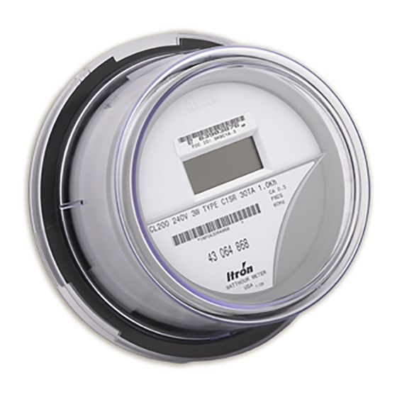
Itron Centron Manuals
Manuals and User Guides for Itron Centron. We have
1
Itron Centron manual available for free PDF download: Technical Reference Manual
Itron Centron Technical Reference Manual (100 pages)
Brand:
Itron
| Category:
Measuring Instruments
| Size: 2 MB
Table of Contents
Trademarks Used in this Manual
2
Compliance with FCC Regulations
3
FCC Part 15, Subpart C
3
RF Exposure Information
3
Canadian Interference Causing Equipment Regulations
4
Factory Repair of Meters
4
Repair of Meters under Warranty
4
Repair of Meters Not under Warranty
4
Service Return Address
4
Recycling Information
4
Table of Contents
5
General Information
11
About this Manual
11
General Description
12
Physical Description
13
Meter Base
13
Figure 1: CENTRON Personality Modules
13
Personality Modules
14
Figure 2: CENTRON 120 Volt Metrology
14
Figure 3: CENTRON 240 Volt Metrology
14
Figure 4: CENTRON 20 Amp Metrology
14
Product Availability
15
Battery
15
Figure 5: CENTRON Personality Module Assembly
15
Covers
16
Display Functions
16
Specifications
16
Electrical
16
Operating Environment
16
Characteristic Data
17
Burden Data
17
Technical Data
18
Dimensions
18
Figure 6: Dimensions
18
C1SD/C1ST/C1SL Dimensions
19
Shipping Weights
19
Figure 7: C12.19 C1SD/T/L C1SR2/R3 Dimensions
19
Chapter 2
21
Inspection
21
Battery
21
Installation
21
Storage
21
Installing the Meter into Service
22
Selecting a Site
22
Unpacking
22
Programming the C12.19 C1SD,T, L Meter
23
Retrofitting with Personality Modules
23
Figure 8: Removing the Board-To-Board Connector
24
Figure 10: Circuit Board Notches
25
Figure 9: New Module Snap-In
25
Figure 11: Board-To-Board Connector, Bottom
26
Figure 12: Board-To-Board Connector, Top
26
Operation: Base Metrology
27
CENTRON 1S, 2S CL200, and 3S
27
Figure 13: Power Measurement Principle in 2S Meter
28
Figure 14: Simplified CENTRON Architecture
28
Centron 2S Cl320, 4S, 12/25S
29
Figure 15: Hall Cells and Adcs
30
Figure 16: C1S LCD Personality Module
31
Operation: C1S Version
31
Chapter 4
32
Physical Description (Personality Modules)
32
Registers
32
Kilowatt Hours
32
Figure 17: Mounted C12.19 D/T/L Register
32
Resetting Values (ZRO-C2A)
33
Figure 18: ZRO-C2A Resetter Connected to the CENTRON
33
LCD Display Function
34
Figure 19: Reverse Side of ZRO-C2A Resetter
34
Figure 20: LCD
34
Non-Detented Register
35
Detented Register
35
Net Register
35
Figure 21: Non-Detented Register
35
Figure 22: Delivered Kwh with Detent Enabled
35
Figure 23: Net Kwh
35
Segment Check
36
Factory Programming Options
36
Display Timing
36
Digits and Multipliers
36
Figure 24: Segment Check
36
Figure 25: CENTRON C1SR Meter
37
Operation: C1SR Version
37
Chapter 5
38
Standard Consumption Message (SCM)
38
Interval Data Message (IDM)
38
Physical Description (C1SR)
38
C1SR Display
39
Figure 26: C1SR LCD
39
C1SR Electronic Detent
40
Net Metering
40
Resetting Values (C1SR)
41
Transmission
41
FCC Regulations
41
Testing the RF Message
41
Tamper Detection
42
Testing the C1SR Tamper Counter
42
SCM Testing
42
Retrofitting the C1SR Personality Module
43
Figure 27: C1SR FCC Label Location
44
Figure 28: CENTRON C1SC
45
Operation: C1SC Version
45
Chapter 6
46
Physical Description
46
Transmission Scheme
46
FCC Regulations
47
Display Functions
47
Figure 29: Cellnet Telemetry
47
Resetting Values
48
Programming the C1SC/CN1SC
48
Figure 30: C1SC LCD
48
Figure 31: C1SC/CN1SC Programming Port Location
49
Figure 32: CENTRON C1SL Meter
51
Operation: C12.19 C1SD, C1ST, and C1SL Versions
51
Chapter 7
52
Features
52
Type Codes
52
Controls and Indicators
53
Figure 33: Controls and Indicators
53
Modes of Operations
54
Normal Mode
54
Alternate Mode
54
Test Mode
55
Test Mode Timeout
55
Test Mode Lockout
55
Displays
55
Optical Port
57
Programmable Functions
57
Energy Data Display Items
57
Demand Data Display Items
57
Informational Data Display Items
57
Demand Registers
59
Demand Calculations
59
Demand
59
Block Interval Demand Calculation
60
Rolling/Sliding Demand Interval Calculation
60
Thermal Emulation
60
Cumulative Demand Values
61
Continuous Cumulative Demand Values
61
Present Demand
61
Previous Demand
61
Projected Demand
62
Peak Demand (Maximum Demand)
62
Coincident Demand
62
Multiple Peaks
62
Demand Reset
62
Cold Load Pickup
63
Tou/Load Profile Meters
63
Self Reading and Snapshot Registers
63
Time-Of-Use
64
TOU Schedules
64
Calendar Schedule
65
Registers
66
TOU Operation
66
Load Profile Specifications
67
Capacity
67
Bit Resolution
67
Interval Lengths
68
Power Outage
68
Channel Configurations
68
Data Storage
69
Recording Duration
70
Optional Features
70
Event Log
70
Security Codes
71
Firmware Upgrades
72
Power Procedures
72
Applying Power
72
Power down Procedures
72
Battery Life (Load Profile & TOU)
73
Three Button Reset
73
RF Options
74
Testing, Troubleshooting, and Maintenance
77
Chapter 8
78
Testing Support Features
78
Infrared Test LED
78
Pulse Detector
78
Figure 34: Test LED Location
78
Annunciators
79
Watthour Annunciators
79
Figure 35: Pulse Detector
79
TOU Rate Annunciators
80
Test Mode Annunciator
80
Testing with the Infrared Test LED
80
Figure 36: TOU Rate Annunciator
80
Testing Using the Disk Emulation Annunciator
81
Recommended Energy Testing Procedures
81
AEP Test Codes
81
Field Testing
81
Required Hardware
82
Test Method Using a Snap Switch Assembly
82
Troubleshooting
82
Fatal Errors
82
Error Codes (C1SR)
82
Error Codes (C12.19 C1SD/T/L)
82
Non-Fatal Errors
84
Inspecting and Troubleshooting-General
86
Blank Display
86
Time and Date Wrong (TOU Version)
86
No Accumulation of Kwh or Kw
86
Software Cannot Communicate with Module
87
Reed Switch Does Not Activate the Alternate Mode
87
Reset Mechanism Does Not Initiate Demand Reset
88
Demand Reset Cannot be Initiated through PC or Handheld
88
Test Mode Switch Does Not Place Meter in Test Mode
88
Inspecting and Troubleshooting-C1S LCD and C1SR
88
Blank Display
88
Specifications and Drawings
89
Specifications
89
Drawings
89
Figure 37: Form 1S Wiring Diagram
89
Figure 38: Form 2S Wiring Diagram
90
Figure 39: Form 3S 120V Wiring Diagram
90
Figure 40: Form 3S 240V Wiring Diagram
91
Figure 41: Form 4S Wiring Diagram
91
Figure 42: Form 12S Wiring Diagram
92
Figure 43: Form 25S Wiring Diagram
92
Glossary of Terms
93
Index
97
Advertisement
Advertisement
Related Products
ITRON CENTRON C1S
ITRON CENTRON C1ST
ITRON CCU 100
ITRON SHARPFLOW CWB7
ITRON CENTRON CP1S
ITRON CENTRON CP1SR
ITRON CENTRON CP1SD
ITRON CENTRON CP1ST
ITRON CENTRON CP1SL
ITRON CENTRON C1SD
Itron Categories
Measuring Instruments
Control Unit
Controller
Data Loggers
Industrial Equipment
More Itron Manuals
Login
Sign In
OR
Sign in with Facebook
Sign in with Google
Upload manual
Upload from disk
Upload from URL