Intel DQ57TML Manuals
Manuals and User Guides for Intel DQ57TML. We have 5 Intel DQ57TML manuals available for free PDF download: Specification, Product Manual
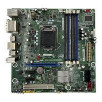
Intel DQ57TML Product Manual (90 pages)
Desktop Board
Brand: Intel
|
Category: Motherboard
|
Size: 6 MB
Table of Contents
Advertisement
Intel DQ57TML Specification (97 pages)
Desktop Board
Brand: Intel
|
Category: Motherboard
|
Size: 3 MB
Table of Contents

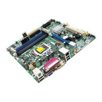
Intel DQ57TML Specification (8 pages)
Desktop Board
Brand: Intel
|
Category: Motherboard
|
Size: 0 MB
Table of Contents
Advertisement

() Intel DQ57TML Product Manual (90 pages)
Simplified Chinese Product Guide
Brand: Intel
|
Category: Motherboard
|
Size: 5 MB
Table of Contents

() Intel DQ57TML Product Manual (88 pages)
Simplified Chinese Product Guide
Brand: Intel
|
Category: Motherboard
|
Size: 4 MB
Table of Contents
Advertisement