Sign In
Upload
Manuals
Brands
INTEL Manuals
Motherboard
BLKD955XBKLKR - 10PK 955X LGA775 8GB DDR2 16X
INTEL BLKD955XBKLKR - 10PK 955X LGA775 8GB DDR2 16X Manuals
Manuals and User Guides for INTEL BLKD955XBKLKR - 10PK 955X LGA775 8GB DDR2 16X. We have
1
INTEL BLKD955XBKLKR - 10PK 955X LGA775 8GB DDR2 16X manual available for free PDF download: Manual
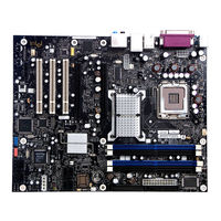
INTEL BLKD955XBKLKR - 10PK 955X LGA775 8GB DDR2 16X Manual (94 pages)
Brand:
INTEL
| Category:
Motherboard
| Size: 0.66 MB
Table of Contents
Technical Product Specification
1
Revision History
2
Intended Audience
3
Typographical Conventions
3
Table of Contents
5
Tables
10
1 Product Description
10
Overview
10
Feature Summary
10
Manufacturing Options
11
Product Description
11
Board Layout
12
Desktop Board Components
12
Figures
12
Components Shown in Figure 1
13
Block Diagram
14
Online Support
15
Processor
15
System Memory
16
Supported Memory Configurations
16
Memory Configurations
17
Memory Channel and DIMM Configuration
17
Dual Channel (Interleaved) Mode Configuration with Two Dimms
18
Dual Channel (Interleaved) Mode Configuration with Three Dimms
18
Dual Channel (Interleaved) Mode Configuration with Four Dimms
19
Single Channel (Asymmetric) Mode Configuration with One DIMM
20
Single Channel (Asymmetric) Mode Configuration with Three Dimms
20
Intel ® 955X Chipset
21
Usb
21
IDE Support
21
Real-Time Clock, CMOS SRAM, and Battery
23
SCSI Hard Drive Activity LED Connector (Optional)
23
Discrete Serial ATA Interface (Optional)
24
PCI Express Connectors
24
Auxiliary Power (AUX PWR) Output Connector (Optional)
25
IEEE-1394A/B Connectors (Optional)
25
I/O Controller
26
Serial Port
26
Parallel Port
26
Diskette Drive Controller
26
Keyboard and Mouse Interface
26
Audio Subsystem
27
Audio Subsystem Software
27
Audio Connectors
27
8-Channel (7.1) Audio Subsystem
28
Front/Back Panel Audio Connector Options for 8-Channel (7.1) Audio Subsystem
28
Channel (7.1) Audio Subsystem Block Diagram
29
6-Channel (5.1) Audio Subsystem
30
Front/Back Panel Audio Connector Options for 6-Channel (5.1) Audio Subsystem
30
Channel (5.1) Audio Subsystem Block Diagram
30
LAN Connector LED States
31
Alert Standard Format (ASF) Support
32
Intel ® Active Management Technology (AMT) (Optional)
32
LAN Subsystem Software
34
LAN Subsystem
31
Intel ® 82573E/82573V/82574V Gigabit Ethernet Controller
31
LAN Connector with Integrated Leds
31
LAN Connector LED Locations
31
Hardware Management Subsystem
34
Hardware Monitoring and Fan Control ASIC
34
Thermal Monitoring
35
Sensors and Fan Connectors
35
Fan Monitoring
36
Chassis Intrusion and Detection
36
Power Management
36
Acpi
36
Effects of Pressing the Power Switch
37
Power States and Targeted System Power
38
Hardware Support
39
Wake-Up Devices and Events
39
Fan Connectors
40
Lan Wake Capabilities
40
Power Connector
40
Location of the Standby Power Indicator LED
42
Trusted Platform Module (Optional)
43
What this Chapter Contains
45
Technical Reference
45
Memory Resources
45
Addressable Memory
45
What this Chapter Contains
45
Detailed System Memory Address Map
46
Memory Map
47
DMA Channels
47
System Memory Map
47
Fixed I/O Map
48
PCI Configuration Space Map
49
Interrupts
50
PCI Conventional Interrupt Routing Map
51
PCI Interrupt Routing Map
52
Connectors
53
Back Panel Connectors
53
Back Panel Connectors for 8-Channel (7.1) Audio Subsystem
54
Back Panel Connectors Shown in Figure 17
54
Back Panel Connectors for 6-Channel (5.1) Audio Subsystem
55
Back Panel Connectors Shown in Figure 18
55
Component-Side Connectors
56
D955XBK Component-Side Connectors
56
Component-Side Connectors Shown in Figure 19
57
ATAPI CD-ROM Connector (Optional)
58
Front Panel Audio Connector
58
Front Chassis Fan and Rear Chassis Fan Connectors
58
Processor Fan Connector and Auxiliary Rear Fan Connector
58
Chassis Intrusion Connector
59
Serial ATA Connectors
59
Auxiliary Power Output Connector
59
Power Supply Connectors
60
Main Power Connector
61
Processor Power Connector (2 X 4 Pin)
61
Alternate Power Connector
61
Auxiliary Front Panel Power/Sleep LED Connector
62
Connection Diagram for Front Panel Connector
63
Front Panel Connector
63
States for a One-Color Power LED
64
States for a Two-Color Power LED
64
Connection Diagram for Front Panel USB Connectors
65
Connection Diagram for Front Panel IEEE 1394A/B Connectors
66
Jumper Block
67
Location of the Jumper Block
67
BIOS Setup Configuration Jumper Settings
67
Mechanical Considerations
68
Form Factor
68
Board Dimensions
68
I/O Shield
69
I/O Shield Dimensions for Boards with the 8-Channel (7.1) Audio Subsystem
69
I/O Shield Dimensions for Boards with the 6-Channel (5.1) Audio Subsystem
70
Electrical Considerations
71
DC Loading
71
Add-In Board Considerations
71
DC Loading Characteristics
71
Fan Connector Current Capability
72
Power Supply Considerations
72
Thermal Considerations
73
Example of a Processor Heatsink for Omni-Directional Airflow
73
Localized High Temperature Zones
74
Reliability
75
Thermal Considerations for Components
75
Environmental
76
Environmental Specifications
76
Regulatory Compliance
77
Safety Regulations
77
EMC Regulations
77
European Union Declaration of Conformity Statement
78
Recycling Considerations
79
Product Certification Markings (Board Level)
80
Product Certification Markings
80
What this Chapter Contains
81
Overview of BIOS Features
81
Introduction
81
Resource Configuration
82
PCI Autoconfiguration
82
PCI IDE Support
82
BIOS Setup Program Menu Bar
82
BIOS Setup Program Function Keys
82
System Management BIOS (SMBIOS)
83
Legacy USB Support
83
BIOS Updates
84
Language Support
84
Custom Splash Screen
84
Boot Options
85
CD-ROM Boot
85
Network Boot
85
Booting Without Attached Devices
85
Changing the Default Boot Device During POST
85
Boot Device Menu Options
85
Fast Booting Systems with Intel ® Rapid BIOS Boot
86
Fast Booting Systems with Intel Rapid BIOS Boot
86
Intel Rapid BIOS Boot
86
Peripheral Selection and Configuration
86
BIOS Security Features
87
Supervisor and User Password Functions
87
Error Messages and Beep Codes
89
Speaker
89
BIOS Beep Codes
89
BIOS Error Messages
89
Beep Codes
89
Port 80H POST Codes
90
Port 80H POST Code Ranges
90
Port 80H POST Codes
91
Typical Port 80H POST Sequence
94
Advertisement
Advertisement
Related Products
Intel BLKD955XCSLKR
Intel BLKD915PSYL - LGA775 800FSB 4DDR Audio Lan SATA uATX
Intel BLKD925XBCLK
Intel BLKD945GCCRL
Intel BLKD945GCLF2D
Intel BLKD945GCPE - LGA775 1066FSB 2DDR2 2GB Audio Video Lan mATX 10Pack Motherboard
Intel BLKD945GNTLR
Intel BLKD945GNTLKR
Intel BLKD945GPMLKR
Intel BLKD945GSEJT
INTEL Categories
Motherboard
Computer Hardware
Server
Server Board
Desktop
More INTEL Manuals
Login
Sign In
OR
Sign in with Facebook
Sign in with Google
Upload manual
Upload from disk
Upload from URL