Sign In
Upload
Manuals
Brands
Inovance Manuals
Servo Drives
SV660NS5R5I-FS
Inovance SV660NS5R5I-FS Manuals
Manuals and User Guides for Inovance SV660NS5R5I-FS. We have
1
Inovance SV660NS5R5I-FS manual available for free PDF download: Advanced User's Manual
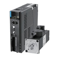
Inovance SV660NS5R5I-FS Advanced User's Manual (426 pages)
Brand:
Inovance
| Category:
Servo Drives
| Size: 77.41 MB
Table of Contents
Preface
2
Unpacking Inspection
2
Revision History
2
Standards Compliance
3
Table of Contents
4
Safety Instructions
11
Safety Precautions
11
Safety Levels and Definitions
11
Safety Signs
15
Product Information
16
Introduction to the Servo Drive
16
Nameplate and Model Number
16
Components
17
Technical Specifications
20
Specifications of the Regenerative Resistor
24
Introduction to the Servo Motor
25
Motor Nameplate and Model Number
25
Components
26
Technical Specifications
27
Servo System Configurations
32
Cable Models
33
Communication Cable Options
35
Connector Kit
35
Servo System Wiring Diagram
36
Installation
38
Installation of the Servo Drive
38
Installation Location
38
Environment Conditions
39
Dimension Drawings
39
Installation
41
Installation of the Servo Motor
43
Installation Location
43
Environment Conditions
43
Installation Precautions
44
Dimension Drawings
46
Wiring
50
Terminal Pin Layout
52
Wiring of the Main Circuit
53
Main Circuit Terminals
53
Wiring Example of the Regenerative Resistor
55
Recommended Models and Specifications of Main Circuit Cables
55
Power Supply Wiring Example
58
Precautions for Main Circuit Wiring
59
Specifications of Main Circuit Options
60
Connection of the Servo Drive and Servo Motor Power Cables
61
Connection of the Servo Drive and Servo Motor Encoder Cables
63
Connection of the Control Signal Terminal CN1
69
DI/DO Signals
70
Wiring of the Brake
73
Wiring of Communication Signals CN3/CN4
75
Pin Definition of the Communication Signal Connector
76
Selection of Communication Cables
76
Communication Connection with PC (RS232 Communication)
77
Definition and Connection of STO Terminal
79
Anti-Interference Measures for Electrical Wiring
81
Anti-Interference Wiring Example and Grounding
82
Instructions for Use of the Noise Filter
83
Precautions for Use of Cables
84
Keypad Display and Operations
86
Introduction to the Keypad
86
Display
86
1Transition Relation between Keypad Display and Operation Objects
87
Display Mode Switchover
87
Status Display
88
Parameter Display
88
Fault Display
90
Monitoring Display
91
Parameter Setting
98
User Password
99
General Functions
100
Jog
100
Forced DI/DO Signals
101
Commissioning and Operation
109
Pre-Running Check
110
Power-On
110
Jog
110
General Parameter Settings
111
Rotation Direction
111
Brake Settings
112
Regenerative Resistor Settings
117
Servo Running
123
Servo Stop
129
Conversion Factor Setting
133
Gain Tuning
136
Overview
136
Inertia Auto-Tuning
137
Offline Inertia Auto-Tuning
138
Online Auto-Tuning
140
Instructions for Etune Operations
140
Overview
141
Description of Operations
141
Precautions
145
Troubleshooting
146
Instructions for Stune Operations
146
Overview
146
Description of Operations
147
Precautions
148
Manual Gain Tuning
150
Basic Parameters
150
Gain Switchover
153
Comparison of Filters
157
Feedforward Gain
158
Pseudo Derivative Feedback and Feedforward Control
159
Torque Disturbance Observation
160
Speed Observer
161
Model Tracking
163
Friction Compensation
166
Parameter Adjustment in Different Control Modes
167
Parameter Adjustment in the Position Control Mode
167
Parameter Adjustment in the Speed Control Mode
169
Parameter Adjustment in the Torque Control Mode
169
Vibration Suppression
169
Suppression of Mechanical Resonance
170
Low Frequency Suppression at the Mechanical End
174
Mechanical Characteristic Analysis
176
Overview
176
Operating Procedures
177
Control Mode
179
Servo Drive State Setting
180
Control Word 6040H
182
Status Word 6041H
183
Servo Mode Setting
184
Introduction to Servo Drive Modes
184
Communication Cycle
186
Cyclic Synchronous Position Mode (CSP)
186
Configuration Block Diagram
186
Related Objects
186
Related Function Settings
187
Recommended Configuration
187
Related Parameters
188
Function Block Diagram
190
Cyclic Synchronous Velocity (CSV) Mode
191
Configuration Block Diagram
191
Related Objects
191
Related Function Settings
191
Recommended Configuration
192
Related Parameters
192
Function Block Diagram
194
Cyclic Synchronous Torque Mode (CST)
195
Configuration Block Diagram
195
Related Objects
195
Related Function Settings
196
Recommended Configuration
198
Related Parameters
198
Profile Position (PP) Mode
200
Function Block Diagram
200
Configuration Block Diagram
201
Related Objects
204
Related Function Settings
204
Recommended Configuration
207
Related Parameters
207
Profile Velocity Mode (PV)
210
Configuration Block Diagram
210
Related Objects
210
Function Block Diagram
210
Related Function Settings
211
Recommended Configuration
214
Related Parameters
214
Profile Torque Mode (PT)
216
Configuration Block Diagram
216
Function Block Diagram
216
Related Objects
217
Related Function Settings
217
Related Parameters
221
Recommended Configuration
222
Function Block Diagram
222
Homing Mode (HM)
223
Configuration Block Diagram
223
Related Objects
223
Related Function Settings
224
Homing Operation
226
Related Parameters
264
Recommended Configuration
267
Function Block Diagram
268
Auxiliary Functions
268
Touch Probe Function (Latch Function))
268
Software Limit
271
Position Comparison
273
Absolute System
279
Descriptions for Use of the Absolute System
279
Absolute Position Linear Mode
281
Absolute Position Rotation Mode
283
Single-Turn Absolute Mode
286
Precautions for Use of the Battery Box
288
Overview of the Ethercat Protocol
289
Communication Configurations
289
System Parameters
290
Parameter Address Structure
290
System Parameter Settings
290
Ethercat Communication Basis
291
Ethercat Communication Specifications
291
Communication Structure
291
State Machine
292
Process Data
293
Service Data Object (SDO)
297
Distributed Clock (DC)
298
Status Indication
298
Overview of Cia402
300
Basic Characteristics
301
Troubleshooting
303
Faults and Warnings
303
Communication Faults and Warning Codes
303
Solutions to Faults
306
Solutions to Warnings
329
Solutions to Communication Faults
335
Application Cases
338
Case 1 AM600 Series Controller as the Host Controller
338
Case 2 Omron NX1P2 Controller as the Host Controller
344
Case 3 Beckhoff Twincat3 as the Host Controller
356
Appendix
371
Standards Compliance
371
CE Certification
371
Low Voltage Directive Compliance
371
EMC Directive Compliance
372
Definition of EMC Terms
373
Selection of EMC Filters
373
Cable Requirements and Routing
378
Solutions to Leakage Current
379
Solutions to Common EMC Problems
380
UL Certification
381
List of Object Groups
382
Description of Object Groups
382
Object Group 1000H
382
Object Group 2000H
388
Object Group 6000H
406
SDO Abort Transfer Code
410
Safety Protection Function: STO
411
Description of Technical Terms
411
Standards Compliance
414
General Safety Information
415
Specifications
416
Installation
417
Terminal and Wiring
417
Requirement for Commission, Operation and Maintenance
417
Safety Function: STO
419
Trouble Shooting
422
Product Information
422
Precautions
424
Advertisement
Advertisement
Related Products
Inovance SV660N Series
Inovance SV660NS1R6I-FS
Inovance SV660NT021I-FS
Inovance SV660NS2R8I-FS
Inovance SV660NS7R6I-FS
Inovance SV660NS012I-FS
Inovance SV660NT8R4I-FS
Inovance SV660NT012I-FS
Inovance SV660FT3R5I
Inovance SV660FS012I-FS
Inovance Categories
DC Drives
Controller
Servo Drives
Control Unit
Inverter
More Inovance Manuals
Login
Sign In
OR
Sign in with Facebook
Sign in with Google
Upload manual
Upload from disk
Upload from URL