Sign In
Upload
Manuals
Brands
Ingersoll-Rand Manuals
Engine
HP750WCU
Ingersoll-Rand HP750WCU Manuals
Manuals and User Guides for Ingersoll-Rand HP750WCU. We have
2
Ingersoll-Rand HP750WCU manuals available for free PDF download: Operating, Maintenance And Parts Manual, Operation & Maintenance Manual
Ingersoll-Rand HP750WCU Operating, Maintenance And Parts Manual (331 pages)
Brand:
Ingersoll-Rand
| Category:
Engine
| Size: 12 MB
Table of Contents
Table of Contents
2
Foreword
3
Safety Information
4
Decals
7
Warranty
14
Noise Emission
18
Maintenance Schedule
20
General Data
22
Operating Instructions
23
Commissioning
23
Compressor Mounting
23
Prior to Starting
23
Prior to Starting
24
Control Panel
25
Stopping
25
Diagnostics Display Panel
26
Starting the Machine
27
Push after Warm up
27
Dual Pressure Regulation When Fitted
27
Stopping the Machine / Emergency Stopping
27
Re-Starting after an Emergency
28
Monitoring During Operation
28
Decommissioning
28
How to Use the Manual
34
Symbols
35
General Safety Instructions
37
General Cleaning Instructions
38
General Repair Instructions
38
Acronyms and Abbreviations
40
Engine and System Identification
41
Engine Dataplate
42
Cummins Engine Nomenclature
43
Fuel Injection Pump Dataplate
43
Engine Diagrams
44
Fuel Pump Side View
44
Rear View
45
Exhaust Side View
46
Front View
47
Top View
48
Operating Instructions
49
Normal Starting Procedure
51
Jump Starting
53
Cold Weather Starting
54
Operating the Engine
54
Starting Procedure after Extended Shutdown or Oil Change
54
Using Starting Aids
54
Ambient Temperature
56
Cold Weather
56
Engine Operating Range
57
Engine Shutdown
57
Maintenance Guidelines
58
Tool Requirements
59
Maximum Oil Drain Intervals
60
Maintenance Procedures at Daily Interval
62
Daily Maintenance Procedures - Overview
63
Air Intake Piping Check
64
Coolant Level Check
64
Drive Belts Check
65
Fan, Cooling - Inspect for Reuse
66
Fuel-Water Separator Drain
67
Crankcase Breather Tube Check
68
Lubricating Oil Level Check
68
Air Tanks and Reservoirs
69
Maintenance at 10,000 Kilometers [6000 Miles]/250 Hours/3 Months
70
Air Cleaner Restriction Check
71
Air Compressor Check
71
Maintenance Procedures - Overview
71
Charge-Air Cooler Check
72
Charge-Air Piping Check
72
Lubricating Oil and Filters
73
Maintenance Procedures at 19,000 Kilometers, 500 Hours, or 6 Months
77
Coolant Filter Removal
78
Coolant Filter Installation
79
Antifreeze
80
Supplemental Coolant Additive (SCA) and Antifreeze Concentration Check
80
Fuel Filter (Spin-On Type) Removal and Installation
81
Fuel Filter (Spin-On Type) Priming
82
Maintenance Procedures at 38,000 Kilometers 1000 Hours, or 1 Year
84
Cooling Fan Belt Tensioner Check
85
Overhead Set Adjustment
86
Maintenance Procedures at 77,000 Kilometers, 2000 Hours, or 2 Years
90
Air Compressor Discharge Lines Check
91
Air Compressor Discharge Lines
92
Cooling System Draining
93
Cooling System Flushing
94
Fill
94
Cooling System Filling
95
Maintenance Procedures - Overview
95
Vibration Damper, Rubber - Inspection
96
Adjustment, Repair, and Replacement
97
Alternator Removal
98
Preparatory Steps
98
Remove
98
Alternator Testing
99
System Diagrams
103
General Information
104
Flow Diagram, Fuel System
105
Flow Diagram, Lubricating Oil System
106
Alternator Installation
109
Charge-Air Cooler
109
Initial Check
109
Charge-Air Cooler Cleaning
110
Charge-Air Cooler Removal
110
Charge-Air Cooler Installation
111
Charge-Air Cooler Pressure Test
111
Charge-Air Cooler Leak Test
112
Charge-Air Cooler Temperature Differential Test
113
Drive Belt, Cooling Fan Removal
113
Remove
113
Cooling Fan Belt Tensioner Removal
114
Drive Belt, Cooling Fan Installation
114
Inspect for Reuse
114
Preparatory Steps
114
Remove
114
Cooling Fan Belt Tensioner Inspection and Installation
115
Inspect for Reuse
115
Fan Spacer and Pulley Removal and Inspection
116
Inspect for Reuse
116
Preparatory Steps
116
Remove
116
Fuel Filter Adapter Removal
117
Install
117
Remove
117
Fuel Filter Adapter Installation
118
Fuel Lift Pump Removal
118
Remove
118
Clean
119
Fuel Lift Pump Installation
119
Fuel Manifold (Drain) Removal
119
Preparatory Steps
119
Remove
119
Fuel Shutoff Valve Removal and Installation
120
Preparatory Steps
120
Remove
120
Lubricating Oil Pressure Regulator (Main Rifle)
121
Preparatory Steps
121
Clean
122
Lubricating Oil Thermostat
122
Remove
122
Starting Motor Check
123
Starting Motor Removal and Installation
124
Starting Motor Rotation Check
125
Air in Fuel
126
Flow Diagram, Cooling System
128
Flow Diagram, Air Intake System
132
Flow Diagram, Exhaust System
133
Flow Diagram, Compressed Air System
134
Troubleshooting Symptoms
168
Air Compressor Air Pressure Rises Slowly
170
Air Compressor Cycles Frequently
171
Air Compressor Noise Is Excessive
172
Air Compressor Pumping Excess Lubricating Oil into the Air System
173
Air Compressor will Not Maintain Adequate Air Pressure
174
Air Compressor will Not Stop Pumping
175
Alternator Not Charging or Insufficient Charging
176
Alternator Overcharging
177
Coolant Contamination
178
Coolant Loss - External
179
Coolant Temperature above Normal - Gradual Overheat
180
Coolant Temperature Is above Normal - Sudden Overheat
182
Coolant Temperature Is below Normal
183
Engine Acceleration or Response Poor
184
Engine Difficult to Start or will Not Start (Exhaust Smoke)
186
Engine Difficult to Start or will Not Start (no Exhaust Smoke)
188
Engine Noise Excessive
190
Engine Noise Excessive - Combustion Knocks
191
Engine Power Output Low
192
Engine Runs Rough at Idle
195
Engine Runs Rough or Misfires
196
Engine Speed Surges at Low or High Idle
197
Engine Speed Surges under Load or in Operating Range
198
Engine Starts but will Not Keep Running
199
Engine Vibration Excessive
200
Engine will Not Crank or Cranks Slowly (Air Starter)
201
Engine will Not Reach Rated Speed (RPM)
204
Engine will Not Shut off
206
Exhaust Smoke Excessive under Load
207
Fuel Consumption Excessive
208
Fuel in the Lubricating Oil
209
Fuel or Lubricating Oil Leaking from Exhaust Manifold
210
Intake Manifold Air Temperature above Specification
211
Intake Manifold Pressure (Boost) Is below Normal
212
Lubricating Oil Consumption Excessive
213
Lubricating Oil Contaminated
214
Lubricating Oil Loss
215
Lubricating Oil Pressure High
216
Lubricating Oil Pressure Low
217
Lubricating Oil Sludge in the Crankcase Excessive
218
Smoke, Black - Excessive
219
Smoke, White - Excessive
220
Turbocharger Leaks Engine Oil or Fue
221
Maintenance Specifications
222
Lubricating Oil Recommendations and Specifications
225
Coolant Recommendations and Specifications
227
Cooling System Additives
230
Cooling System Sealing Additives
232
Cooling System Soluble Oils
232
Drive Belt Tension
233
Engine Component Torque Values
233
Sealants
234
Capscrew Markings and Torque Values
235
Index
247
Routine Maintenance
252
Portable Compressor Fluid Chart
256
Speed and Pressure Regulation Adjustment
257
Torque Setting Table
258
Fault Finding
260
General Arrangement Diagram
264
HSRG Frame Assembly Diagram
265
HSRG Belly Pans Diagram
266
Drawbar Jack Assembly Diagram
267
Brake Actuator Assembly Diagram
268
Hydraulic Brake Piping Diagram
269
Parking Brake Assembly (HSRG) Diagram
270
High Speed Running Gear Diagram
271
Hydraulic Brakes (with Park Brake - Front Axle) Diagram
273
Hydraulic Brakes (no Park Brake - Front Axle) Diagram
274
Hydraulic Brakes (with Park Brake - both Axles) Diagram
275
Running Lights Assembly Diagram
276
Steerable Frame and Bellypans Diagram
277
Steerable Running Gear Diagram
278
Engine Complete Diagram
283
Regulation/Air Cylinder Diagram
284
Ether Cold Start Kit Diagram
285
Exhaust Complete Diagram
286
Air End Complete Diagram
287
Air End Assembly Diagram
288
Unloader Assembly Diagram
292
Radiator and Coolers Mounting Diagram
293
Radiator and Coolers Piping Diagram
294
Fuel Tank Assembly Diagram
295
Fuel Tank Piping Diagram
296
Air Intake Complete Diagram
297
Separator Tank Assembly Diagram
298
Separator Tank Piping Diagram
299
Minimum Pressure Check Valve Assembly Diagram
300
Service Piping (One 2" NPT Valve) Diagram
301
Air Piping Diagram
302
Oil Piping Diagram
304
Compressor Oil Filter Diagram
306
Instrument/Control Panel Assembly Diagram
307
Instrument/Control Panel
308
Instrument Panel Door Assembly Diagram
309
Battery and Mounting Diagram
310
Enclosure (External) Diagram
311
Enclosure (External) Galvaneal Diagram
312
Enclosure Baffles Diagram
313
Acoustic Foam Diagram
314
Decal Location Diagram
315
Electrical Parts List
317
Starter Aid (AC Kit) Diagram
318
Service Piping (One 2" BSP Valve) Diagram
319
Service Manifold Piping (NPT) Diagram
320
Service Manifold Piping (Metric) Diagram
321
Engine Oil Draining Piping Diagram
322
Separator Tank Drain Diagram
323
Oil Cooler Pan Diagram
324
Fuel Tank Drain Diagram
325
Radiator Drain Diagram
326
Securable Lift Eye Diagram
327
Wiring Diagram
328
Advertisement
Ingersoll Rand HP750WCU Operation & Maintenance Manual (68 pages)
Brand:
Ingersoll Rand
| Category:
Compressor
| Size: 1 MB
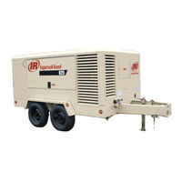
Table of Contents
Table of Contents
3
Foreword
7
Foreword
8
Safety
11
Safety
12
Safety Precautions
12
General Information
12
Compressed Air
13
Materials
14
Battery
15
Radiator
15
Transport
16
Safety Chains/Connections and Their Adjustment Where Fitted
16
Decals
17
Graphic Form and Meaning of ISO Symbols
17
Noise Emission
27
Noise Emission
28
Compressor Noise Emission Control Information
28
Noise Emission Control
29
Maintenance Log
29
Noise Emission Warranty
29
Introduction
30
Maintenance Schedule
30
Compressed Air Leaks
30
Safety and Control Systems
30
Acoustic Materials
30
Fasteners
31
Enclosure Panels
31
Air Intake and Engine Exhaust
31
Cooling Systems
31
Isolation Mounts
31
Engine Operation
31
Fuels and Lubricants
31
General Data
33
General Data
34
Operating Instructions
37
Operating Instructions
38
Commissioning
38
Compressor Mounting
38
Prior to Starting
40
Control Panel
42
Diagnostic Display Panel
43
Starting the Machine
44
Push after Warm up
45
Dual Pressure Regulation When Fitted
45
Stopping the Machine
45
Emergency Stopping
45
Re-Starting after an Emergency
46
Monitoring During Operation
46
Decommissioning
46
Maintenance
47
Maintenance
48
Routine Maintenance
50
Prior to Attempting any Maintenance Work, Ensure that
51
Prior to Opening or Removing Panels or Covers to Work Inside a Machine, Ensure that
51
Prior to Attempting any Maintenance Work on a Running Machine, Ensure that
51
Upon Completion of Maintenance Tasks and Prior to Returning the Machine into Service, Ensure that
52
Protective Shutdown System
52
Low Engine Fuel Level Switch
52
Scavenge Line
52
Compressor Oil Filter
53
Removal
53
Lnspection
53
Reassembly
53
Compressor Oil Separator Element
54
Removal
54
Lnspection
54
Reassembly
54
Compressor Oil Cooler and Engine Radiator
55
Air Filter Elements
56
Removal
56
Reassembly
56
Ventilation
56
Cooling Fan Drive
56
Fuel System
56
Fuel Filter Water Separator
57
Charge Air Cooler Pipework
57
Hoses
57
Electrical System
57
Battery
57
Pressure System
57
Tire Pressure
58
Running Gear/Wheels
58
Lubrication
58
Engine Lubricating Oil
58
Compressor Lubricating Oil
59
Running Gear Wheel Bearings
59
Lubrication
61
Lubrication
62
Portable Compressor Fluid Chart
62
Speed and Pressure Regulation Adjustment
63
Torque Setting Table
64
Torque Setting Table
65
Fault Finding
66
Advertisement
Related Products
Ingersoll-Rand HP675WCU
Ingersoll-Rand HP 7.5
Ingersoll Rand HP 75-100
Ingersoll Rand Doosan HP750WCU-T2
Ingersoll-Rand Doosan HP750WCU-T3
Ingersoll-Rand HP750WJD
Ingersoll-Rand HP750A-WCU
Ingersoll-Rand HP600A-WCU
Ingersoll-Rand HPE300-2S
Ingersoll-Rand HPE250-2S
Ingersoll-Rand Categories
Water Pump
Power Tool
Air Compressor
Impact Driver
Drill
More Ingersoll-Rand Manuals
Login
Sign In
OR
Sign in with Facebook
Sign in with Google
Upload manual
Upload from disk
Upload from URL