Sign In
Upload
Manuals
Brands
Inertial Labs Manuals
Car Navigation system
INS Series
Inertial Labs INS Series Manuals
Manuals and User Guides for Inertial Labs INS Series. We have
1
Inertial Labs INS Series manual available for free PDF download: User Manual
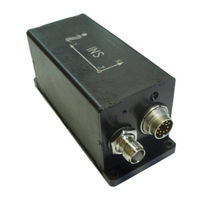
Inertial Labs INS Series User Manual (251 pages)
Inertial Navigation System. Graphical User Interface
Brand:
Inertial Labs
| Category:
Car Navigation system
| Size: 8.48 MB
Table of Contents
Table of Contents
9
Introduction
13
The most Important Notes
15
General Information
17
Installation of Drivers and Configuration of PC Parameters
18
Main Menu of the Program
19
Options Menu
21
Test Options
21
Devices Options
24
IMU" Tab of "Devices Options
25
GNSS Receiver" Tab of "Devices Options
29
Pressure Sensor" Tab of "Devices Options
37
External Sensors" Tab of "Devices Options
38
Parameters of Encoder-Based Odometer
39
Using the Main COM1 Port to Receive External Aiding Data
39
Using External Magnetic Compass
40
CAN / COM4" Tab of "Devices Options
41
Configuration of CAN Messages Output
41
Configuration of COM4 Port
42
Parameters of OBDII Odometer
43
Triggers" Tab of "Devices Options
44
Change of the Main COM Port Baud Rate
45
Limitation of the ins Maximum Output Data Rate
48
Table 4.1 ins Maximum Measurement Rate for Different Output Data Formats
49
Correction Options
51
Swaying Compensation
55
Magnetometers Calibration Options
56
User Defined Data
57
Table 4.2 Groups and Data Types of the "User Defined Data
59
Review and Editing of the Existing Configuration of the "User Defined Data" Format in ins Unit
62
User Defined Data" Format Configuration File (*.Udd)
64
INS Start with "User Defined Data" Output Format
65
Run Menu
65
Ins 3D
66
Cockpit Style of Visualization
72
On-The-Fly Accuracy Style of Visualization
73
Data Graphs Style of Visualization
74
Visualization of ins Relative Position
76
Peculiarities of Data Displayed at the "INS Sensors Data" Format
77
Other Items of the Run Menu
78
File Menu
80
Open" Item
80
Save As" Item
81
Parameters Menu
82
Load Block Parameters" and "Read Block Parameters" Items
82
Restore Parameters
82
Save Parameters
83
Preset Parameters
83
Plugins Menu
86
Embedded
86
Magnetometers Field Calibration
88
Angles Accuracy
90
Magnetometers Axes Alignment
94
Convert Menu
96
The ins Operation
98
The Main Operation Modes of the ins
98
Control of the GNSS Receiver
101
GNSS Correction
101
Table 10.1 Available Variants of SBAS Data
102
Control of GNSS Receiver Model
105
Adding New Model to the GNSS Receiver
106
Choosing of One of Saved Models for the GNSS Receiver
106
Removing Model from the GNSS Receiver
107
Features of Altitude Calculation in the ins
108
Calibration of the ins
109
Description of the 2D, 2D-2T, 3D and VG3D Calibration Procedures
111
Clearing of the Soft and Hard Iron Calibration Parameters
119
Conditions of Successful Calibration of the ins
120
On-The-Fly VG3D Calibration
121
Orientation Accuracy Test of the ins
124
Separate Accuracy Test for each Reference Angle
124
On-The-Fly Accuracy Test
126
Table 10.2 Example of the *.Csv File Created at Accuracy Test
130
INS Automatic Start
131
INS Operation with Odometer
133
INS Operation with OBDII Odometer
133
INS Operation with Encoder-Based Odometer (Wheel Speed Sensor)
134
Encoder-Based Odometer Calibration
135
Operations with CAN Data
137
Table 10.3. List of Supported CAN Messages
140
Review and Editing of the Existing Configuration of the "CAN Message Set" Format in ins Unit
142
CAN Message Set" Format Configuration File (*.Ucan)
143
INS and OS3D-FG SAMC Axes Alignment
144
Description of the Axes Alignment Procedures
144
Table 10.4 Example of Rotation Angles
144
Clearing Axes Alignment Parameters
147
Continuous Self-Monitoring of the ins Health
148
INS and GNSS Data Post-Processing
149
Recording of Raw GNSS Data
149
Table 12.1 Logs for Raw GNSS Data
150
Table 12.2 Minimal Set of Raw GNSS Data Logs
150
Raw IMU Data Generation
153
Table 12.3 Binary Structure of Raw IMU Data
154
Embedding Raw IMU Data into GNSS Stream
157
INS Sensors Error Model for ins + GNSS Data Post-Processing
158
Synchronization of ins Data with Lidar and Other Devices
160
Control of PPS Output Signal
160
Processing of Mark Input Signal
162
INS Operation with Lidar
162
Configuration of ins Main Data
163
Configuration of COM2 Port for Output of GNSS Raw Data
163
Configuration of COM3 Port for Output of $GPRMC Messages
164
Configuration of PPS Signal
164
Configuration of Mark Input Signal
164
Choice of 3D Model for Visualization of the ins Orientation
165
Troubleshooting
166
How to Repair the ins Parameters
166
What Do You Have to Do at Strange Behavior of the ins
166
What Do You Have to Do if Messages "Cannot Read Parameters!", "Cannot Load Parameters!", or "Cannot Start INS" Appear
168
APPENDIX A. Installation of the COM-To-USB Converter Drivers and Configuration of PC Parameters
169
APPENDIX B. Installation of the MOXA Serial-To-USB Converter Drivers (for ins with RS-422 Interface)
177
APPENDIX C. Description of Data Files
184
Structure of Binary File
184
Table C.1 Structure of the First 50 Bytes of *.Bin File (Short Block of Initial Alignment Data)
184
Table C.2 Structure of the First 128 Bytes of *.Bin File at Extended Block of Initial Alignment Data
185
Table C.3 the ins Message Payload at the "INS OPVT" (Orientation, Position, Velocity, Time) Data Format
186
Table C.4 Gnss_Info1 - Information about GNSS Data
187
Table C.5 Gnss_Info2 - Information about GNSS Data
188
Table C.6 New_Gps Indicator of New Update of GNSS Data
188
Table C.7 the ins Message Payload at the "INS QPVT" (Quaternion of Orientation, Position, Velocity, Time) Data Format
189
Table C.8 the ins Message Payload at the "INS OPVT2A" (Orientation, Position, Velocity, Time, Dual-Antenna Receiver Data) Format
191
Table C.9 the ins Message Payload at the "INS OPVT2AW" (Orientation, Position, Velocity, Time, Dual-Antenna Receiver Data, GPS Week) Format
193
Table C.10 the ins Message Payload at the "INS Opvt2Ahr" (Orientation, Position, Velocity, Time, Dual-Antenna Receiver Data, with High Resolution) Data Format
195
Table C.11 the ins Message Payload at the "INS OPVTAD" Data Format
197
Table C.12 New Aiding Data Indicator
199
Table C.13 the Message Payload at the "INS Sensors Data" Format
200
Table C.14 Sol_Stat - GNSS Solution Status
202
Table C.15 Pos_Type - GNSS Position or Velocity Type
202
Table C.16 Ext_Sol_Stat - GNSS Extended Solution Status
203
Table C.17 GPS and GLONASS Signal-Used Mask
203
Table C.18 Galileo and Beidou Signal-Used Mask
203
Table C.20 the Message Payload at the "INS OPVT & Raw IMU Data" Format
204
Table C.19 the Message Payload at the "INS Minimal Data" Format
204
Table C.21 the "SPAN Rawimu" Message Structure
206
Table C.22 GPS Reference Time Status
207
Table C.23 GNSS Receiver Status
207
Table C.25 the ins Message Payload at the "INS OPVT Gnssext" Data Format
208
Table C.24 IMU Status
208
Table C.26 Payload of the "User Defined Data
211
Table C.27 Detailed Description of "User Defined Data" Structure
211
Table C.28 ins Solution Status (Data Type # 0X54)
216
Table C.29. Structure of the "Cobham UAV 200 Satcom" Sentence
218
Text Presentation of Output Data Formats
220
APPENDIX D. the Unit Status Word Definition
236
APPENDIX E. Variants of the Inertial Labstm ins Mounting Relative to Object Axes
238
APPENDIX F. Installation of the GNSS Antennas
241
Installation of Single GNSS Antenna
241
Installation of Two GNSS Antennas for INS-D Operation
243
APPENDIX G. Using of the STRSVR Tool
246
APPENDIX H. Using Ethernet Port for Communication with the Inertial Labstm ins
248
Connection Overview
248
Connection Steps
249
Networking Details
249
Checking the Connection to the Network
249
Creating a Virtual Serial Port
250
Advertisement
Advertisement
Related Products
Inertial Labs INS-P
Inertial Labs INS-B
Inertial Labs INS-P-OEM
Inertial Labs INS-D-OEM
Inertial Labs INS-DL
Inertial Labs INS-B-OEM
Inertial Labs INS-D
Inertial Labs Categories
Accessories
Car Navigation system
More Inertial Labs Manuals
Login
Sign In
OR
Sign in with Facebook
Sign in with Google
Upload manual
Upload from disk
Upload from URL