Sign In
Upload
Manuals
Brands
Imperx Manuals
Digital Camera
Cheetah Pregius POE-C4410
Imperx Cheetah Pregius POE-C4410 Manuals
Manuals and User Guides for Imperx Cheetah Pregius POE-C4410. We have
1
Imperx Cheetah Pregius POE-C4410 manual available for free PDF download: User Manual
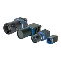
Imperx Cheetah Pregius POE-C4410 User Manual (123 pages)
With GigE Vision Interface
Brand:
Imperx
| Category:
Digital Camera
| Size: 9.14 MB
Table of Contents
Table of Contents
4
1 About the Camera
11
General
11
Key Features
12
Table 1: Cheetah Cameras with Gige Vision® Poe Interface
12
Table 2: C2000 and C2400 Cameras Specifications
13
Table 3: C2010 and C2410 Cameras Specifications
14
C3210 and C4010 Cameras Specifications
15
Table 4: C3210 and C4010 Cameras Specifications
15
C4110 Camera Specifications
16
Table 5: C4110 Camera Specifications
16
C2410Y/Z and C4110Y/Z Cameras Specifications
17
Table 6: C2410Y/Z and C4110Y/Z Cameras Specifications
17
C4410 and C5410 Cameras Specifications
18
Table 7: C4410 and C5410 Cameras Specifications
18
C6410 Camera Specifications
19
Table 8: C6410 Camera Specifications
19
Ordering Information
20
Table 9: Cheetah Camera Ordering Codes
20
Technical Support
21
Figure 1: POE-C2000 and POE-C2400 Camera Back Panel Connectors
22
Pin Assignment
23
C2010 and C2410 Cameras Specifications
14
Technical Specifications
13
C2000 and C2400 Cameras Specifications
13
2 Hardware
22
C2000 and C2400 Cameras Connectivity
22
Figure 2: 6-Pin Hirose Connector Pin-Outs (C2000 and C2400 Cameras)
23
Table 10: 6-Pin Hirose Connector Pin Mapping
23
C2010, C2410, C3210, C4010 and C4110 Cameras Connectivity
24
Figure 3: POE-C2010, POE-C2410, POE-C3210, POE-C4010, and POE-C4110 Camera Back Panel Connectors
24
Figure 4: 12-Pin Hirose Connector Pin-Outs (POE-C2010, POE-C2410, POE-C3210, POE- C4010, POE-C4110, POE-C4410, POE-C5410, and POE-C6410 Cameras)
25
C4410, C5410, C6410 Cameras Connectivity
26
Pin Assignments
26
Pin Assignments
25
Table 11: 12-Pin Hirose Connector Pin Mapping
25
Figure 5: POE-C4410, POE-C5410, and POE-C6410 Camera Back Panel Connectors
26
Figure 6: P67-C2010, P67-C2410, P67-C3210, P67-C4010, and P67-C4110 Camera Back Panel Connectors
27
P67 Cameras Connectivity
27
Figure 7: BULGIN PXMBNI12RPM08APCM12 Connector Pin-Outs (P67-C2010, P67-C2410, P67-C3210, P67-C4010, and P67-C4110 Cameras)
28
Table 12: 8-Pin BULGIN Connector Pin Mapping
28
Ethernet Connector Pin Assignment
29
Figure 8: MACOM MMT361A315 Connector Pin-Outs (P67-C2010, P67-C2410, P67-C3210, P67-C4010, and P67-C4110 Cameras)
29
Table 13: MACOM Connector Pin Mapping
29
Camera LED Status Indicator
30
POE and External Power Supply
30
Table 14: LED Status Indicator Descriptions
30
Figure 9: PS12V04A Power Supply (Ordered Separately)
31
PS12V04A Standard Power Supply
31
Figure 10: CBL-COM01 Cable for Use with C2000 and C2400 Cameras (Ordered Separately)
32
Power and I/O Cable CBL-COM01
32
Figure 11: CBL-PWIO01 Cable (Ordered Separately)
33
I/O Cable PWIO01
33
Active Canon EF Mount
34
Electrical Connectivity
34
Figure 12: the Camera (Left) and Canon EF Lens Mount (Center) Connect Internally
34
Table 15: Inputs and Outputs of the Cheetah Cameras
34
Opto-Isolated Input
35
TTL Output
35
TTL/LVTTL Input
35
C2000 and C2400 Cameras
38
Mechanical Drawings
38
Figure 14: TTL Input Electrical Schematic (Simplified)
35
Figure 13: Opto-Isolated Input Electrical Schematic (Simplified)
35
Figure 15: TTL Output Electrical Schematic (Simplified)
35
Opto-Isolated Output
36
Power and I/O Connector Pin Assignments
28
Figure 17: out 2 Low Side Load Driver Circuit
36
Figure 18: Out2 High Side Load Driver Circuit
37
Figure 20: Front and Back Views of the POE-C2000 and POE-C2400 Cameras
38
Figure 19: POE-C2000 and POE-C2400 Cameras
38
Figure 22: POE-C2010, POE-C2410, POE-C2410Y/Z, POE-C3210, POE-C4010, POE-C4110, POE
40
Figure 23: Front and Back Views of the POE-C2010, POE-C2410, POE-C2410Y/Z, POE-C3210
40
Figure 24: Top and Side Views of the POE-C2010, POE-C2410, POE-C2410Y/Z, POE-C3210
41
C4410, C5410, and C6410 Cameras
42
Figure 25: POE-C4410, POE-C5410, POE-C6410 Cameras
42
Figure 26: Front and Back Views of the POE-C4410, POE-C5410, and POE-C6410 Cameras
42
Figure 27: Top and Side Views of the POE-C4410, POE-C5410, and POE-C6410 Cameras
43
Figure 28: P67-C2010, P67-C2410, P67-C3210, P67-C4010, P67-C4110 Cameras
44
Figure 29: Front and Back Views of the P67-C2010, P67-C2410, P67-C3210, P67-C4010, P67
44
Figure 30: Mechanical Drawings of the P67-C2010, P67-C2410, P67-C3210, P67-C4010, P67
45
Optical
46
Table 16: Cheetah Cameras' Adapters and Back Focal Distances
46
Environmental
47
P67 Cameras Lens Tubes
47
P67 Cheetah Cameras
44
Figure 16: Out2 Open Drain Logic Driver Circuit
36
Figure 21: Bottom and Side Views of the POE-C2000 and POE-C2400 Cameras
39
C2010, C2410, C3210, C4010, and C4110 Cameras
40
Table 17: Lens Tube Specifications
47
3 Genicam TM API Module - Configuring the Camera
48
Camera User Set Description
48
Startup Procedure
48
Genapi Camera Configuration
48
Device Control
49
Overview
48
Table 19: Device Control Parameters
49
Table 18: Parameters Availability
49
Table 21: Image Format Control Parameters
52
Table 22: Slave AOI Parameters
53
Acquisition Control
54
Table 23: Acquisition Control Parameters
54
Gain Control
56
Table 24: Gain Control Parameters
56
Auto Exposure and Auto Gain Control (AEC/AGC)
57
Table 25: Auto Exposure and Auto Gain Control Parameters
57
Table 26: Status Parameters
58
Data Correction
59
Table 27: Data Correction Parameters
59
Table 28: White Balance Parameters
60
White Balance
60
Output and Strobe Signals
61
Table 29: OUT1 Parameters
61
Table 30: OUT2 Parameters (some Cameras May Not Support OUT2)
61
Pulse Generator
62
Table 31: Strobe 1 and Strobe2 Parameters (some Cameras May Not Support Strobe2)
62
Table 32: Pulse Generator Parameters
62
Canon Lens Control
63
Table 20: Version Information Parameters
50
Image Format Control
52
Version Information
50
Table 34: Controller Settings
63
Table 36: Iris Parameters
64
Table 37: Payloadsize Parameter
65
Table 38: Gige Vision Parameters
65
Table 39: User Set Controls Parameters
68
Event Control
69
Table 35: Focus Parameters
64
User Set Controls
68
Table 33: General Canon Lens Control Parameters
63
Transport Layer Information
65
Table 40: Event Control Parameters
69
4 Software GUI
70
Figure 31: Ipxplayer Graphical User Interface
70
Figure 32: Security Screen
71
User Interface and Functionality
71
Overview
70
Supported Operating Systems
70
Compatibility
71
Installing the Software
71
Installation
71
Figure 33: Welcome Setup Screen
72
Figure 34: License Agreement Screen
72
Figure 35: Choose Components Screen
73
Figure 36 Choose Install Location Screen
73
Figure 38: Installation Complete Screen
74
Figure 39: Completing Imperx Camera SDK Setup Screen
74
Figure 40: Ipxplayer Icon
74
Figure 41: Imperx Camera SDK File Locations on Your Computer
75
Connecting to Cameras
76
Figure 42: Connecting to a Camera
76
Figure 43: Select Camera Dialogue
76
Figure 45: Select an Access Level
80
Figure 46: Device Control Parameters
80
Figure 47: Version Info Parameters
81
Version Info Controls
81
Figure 48: Image Format Control Parameters
82
Image Format Controls
82
Figure 49: Slave AOI Parameters
83
Acquisition Control
84
Figure 50: Acquisition Control Parameters
84
Figure 51: Gain Control
86
Gain Controls
86
Auto Gain and Auto Exposure
87
Figure 52: Auto Gain and Auto Exposure
87
Data Correction Controls
89
Figure 53: Data Correction Parameters
89
Figure 54: White Balance Parameters
90
White Balance Controls
90
Figure 55: Strobe Parameters
91
Canon Lens Control
92
Pulse Generator Controls
92
Figure 37: Uninstall any Existing Versions Dialog
73
Figure 44: Access Status Showing IP Subnet Mismatch
77
Using the Ipxplayer
78
Menu Bar
78
Saving and Loading Configurations
79
Camera Parameter Panel
80
Device Control
80
Strobe Controls
91
Figure 56: Pulse Generator Parameters
92
Figure 58: Canon Lens Control - Controller Settings
93
Figure 59: Canon Lens Control - Focus Settings
93
Figure 60: Canon Lens Control - Iris Settings
94
Figure 61: Transport Layer Control
95
Event Control
97
Figure 62: User Set Parameters
97
Figure 63: Event Control Parameters
97
User Set Controls
97
Capture Panel
98
Figure 64: the Capture Panel Saves Images and Video
98
Recording Acquired Images
98
Saving Image Output
98
Channels to Log
99
Figure 65: the Log Panel Records Data Transfers
99
Log Panel
99
Figure 66: Statistics Panel
100
Statistics Panel
100
Figure 57: Canon Lens Control General Parameters
92
Transport Layer Control
95
Camera SDK
75
5 Camera Features
101
Exposure Control
101
Internal Exposure Control - Electronic Shutter
101
Automatic Exposure Control
102
Figure 67: Global Shutter with 8.33Ms Exposure Time
102
Table 41: Acquisition Control Modes
103
Video Amplifier Gain and Offset
104
Black Level Auto-Calibration and Offset
104
Digital Gain
104
Digital Offset
104
Data Output Format
105
Pixel Format
105
Pulse Generator
105
Acquisition Control
103
Automatic Gain Control
103
Figure 69: Internal Pulse Generator
105
Table 42: Output Signals
107
Figure 70: Horizontal and Vertical Window Positioning
108
Bad Pixel Correction
109
Gamma Control
109
Slave AOI
109
Table 43: Slave AOI Modes
109
Dynamic Pixel Correction
110
Flat Field Correction
110
Static Pixel Correction
110
Table 44: Test Patterns
110
Test Image Pattern
110
Color Control
111
Table 45: Automatic White Balance Modes
111
Configuration Memory
112
Area of Interest
108
Factors Impacting Frame Rate
108
Horizontal and Vertical Window
108
Figure 68: 12-Bit Internal Digitization with 12-Bit, 10-Bit, and 8-Bit Outputs
105
Camera Triggering
106
Trigger Modes
106
Trigger Sources
106
Input / Output Control
106
Strobe and Synchronization Controls
107
6 Image Sensor Technology
113
General Information
113
Spectral Sensitivity
114
Micro-Polarized Cameras
114
Figure 71: the POE-C2410Y/Z and POE-C4110Y/Z Cameras Micro-Polarizer Blocks Image Obscuring Light Waves from Reaching the Sensor
114
Appendix A - Spectral Response
115
Cheetah C2000 and C2010 Spectral Response
115
Figure 72: Cheetah C2000 and C2010 Color Spectral Response
115
Figure 74: Cheetah C2400 and C2410 Color Spectral Response
116
Figure 75: Cheetah C2400 and C2410 Monochrome Spectral Response
116
Figure 76: Cheetah C2410Y/Z Color Spectral Response
117
Figure 77: Cheetah C2410Y/Z Monochrome Spectral Response
117
Cheetah C3210 Spectral Response
118
Figure 78: Cheetah C3210 Color Spectral Response
118
Figure 79: Cheetah C3210 Monochrome Spectral Response
118
Cheetah C4010 Spectral Response
119
Figure 80: Cheetah C4010 Color Spectral Response
119
Figure 81: Cheetah C4010 Monochrome Spectral Response
119
Cheetah C4110 Spectral Response
120
Figure 82: Cheetah C4110 Color Spectral Response
120
Figure 83: Cheetah C4110 Monochrome Spectral Response
120
Cheetah C4410 Spectral Response
121
Figure 84: Cheetah C4410 Color Spectral Response
121
Figure 85: Cheetah C4410 Monochrome Spectral Response
121
Cheetah C5410 Spectral Response
122
Figure 86: Cheetah C5410 Color Spectral Response
122
Figure 87: Cheetah C5410 Monochrome Spectral Response
122
Cheetah C6410 Spectral Response
123
Figure 73: Cheetah C2000 and C2010 Monochrome Spectral Response
115
Cheetah C2410Y/Z Spectral Response
117
Cheetah C2400 and C2410 Spectral Response
116
Figure 88: Cheetah C6410 Color Spectral Response
123
Figure 89: Cheetah C6410 Monochrome Spectral Response
123
Advertisement
Advertisement
Related Products
Imperx Cheetah Pregius POE-C4010
Imperx Cheetah Pregius POE-C4110
Imperx Cheetah Pregius POE-C4110Y
Imperx Cheetah Pregius POE-C4110Z
Imperx Cheetah Pregius POE-C2000
Imperx Cheetah Pregius POE-C2400
Imperx Cheetah Pregius POE-C2010
Imperx Cheetah Pregius POE-C2410
Imperx Cheetah Pregius POE-C2410Y
Imperx Cheetah Pregius POE-C2410Z
Imperx Categories
Digital Camera
Security Camera
Color Camera
Computer Hardware
PCI Card
More Imperx Manuals
Login
Sign In
OR
Sign in with Facebook
Sign in with Google
Upload manual
Upload from disk
Upload from URL