Sign In
Upload
Manuals
Brands
ILX Lightwave Manuals
Controller
LDC-3722B
ILX Lightwave LDC-3722B Manuals
Manuals and User Guides for ILX Lightwave LDC-3722B. We have
1
ILX Lightwave LDC-3722B manual available for free PDF download: Instruction Manual
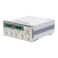
ILX Lightwave LDC-3722B Instruction Manual (269 pages)
LASER DIODE CONTROLLERS
Brand:
ILX Lightwave
| Category:
Controller
| Size: 11 MB
Table of Contents
Table of Contents
5
Chapter 1 . General Information
8
Introduction
8
Product Overview
13
Available Options and Accessories
13
Specifications
14
7 12 Laser Current Source Specifications
14
7 12 Temperature Controller Specifications
17
General LDC-3712 Specifications
17
LDC-3722B Specifications
17
3722B Laser Current Source Specifications
18
3722B Temperature Controller Specifications
19
General LDC-3722B Specifications
21
LDC-3712B Specifications
21
3742B Laser Current Source Specifications
23
General LDC-3742B Specifications
25
Your Comments
25
Chapter 2 . Operation
27
Introduction
27
Installation
27
AC Power Considerations
27
Tilt-Foot Adjustment
27
Rack Mounting
27
Power-Up Sequence
27
LDC-3700 Series Default Settings
28
Introduction to the LDC-3700 Series Front Panel
29
LDC-3722B Front Panel
29
Front Panel Familiarization
30
General Functions
30
TEC Functions
31
LASER Functions
32
GPIB Section
33
ADJUST Section
33
Automatic Set Point Adjustment
34
TEC MODE Section
34
LDC-3700 Series TEC MODE Section
34
Tec Mode Select
35
TEC MODE Indicators
35
Tec Mode on
35
TEC DISPLAY Switch Section
35
LDC-3700 Series TEC DISPLAY Switch Section
35
Tec Display Set
36
TEC DISPLAY Indicators and Switches
36
LDC-3700 Series PARAMETER Section
36
TEC PARAMETER Section
37
Tec Parameter Select
37
Tec Parameter Set
37
Const
38
Gain
38
Bar Graph
39
TEC Error Indicators
39
LASER MODE Section
39
LDC-3700 Series TEC Error Section
39
Laser Mode Select
40
LASER MODE Indicators
40
Laser Mode on
40
LDC-3700 Series LASER MODE Section
40
LASER DISPLAY Switch Section
41
Laser Display Set
41
LDC-3700 Series LASER DISPLAY Switch Section
41
LASER DISPLAY Indicators and Switches
42
Laser Parameter Select
43
Laser Parameter Set
43
Lim I
43
Limp
43
Cal Pd
44
LASER Error Indicators
44
LASER Error Inlcators
44
RANGE Section
45
MOD Section
45
SAVE and RECALL PARAMETERS
45
LDC-3700 Series MOD Sections
45
Back Panel Controls and Connections
46
LDC-3700 Series Back Panel
46
SENSOR SELECT Switch
47
Back Panel TEC Connector
47
Back Panel LD Connector
47
SENSOR SELECT Switch Positions
47
TEC Grounding Considerations
48
Common Laser Anode Photodiode Anode
50
Grounding Considerations
52
GPIB Connector
52
Warm-Up and Environmental Considerations
52
TEC Mode Operation
52
LASER Mode Operation
53
Chapter 3 . Gptsiieee.2 Remote Operation
55
Introduction
55
Preparation for Bus Control
56
ANSLIIEEE-488.2 Definitions
56
Syntax Diagrams
56
White Space
57
Power-On Conditions
57
White Space Syntactic Diagram
57
Program Message Terminator
58
Program Message Unit Separator
58
PROGRAM MESSAGE TERMINATOR> Syntax Diagram
58
PROGRAM HEADER SEPARATOR> Syntax Diagram
59
Compound Command Program Header> Syntax Diagram
59
PROGRAM DATA> (Parameters)
60
Arbitrary Block Program Data
60
Program Data Separators
61
Default Parameters
62
Getting Started with GPIB
63
Overview of the 3700 Series Laser Diode Controller Syntax
63
Using Commands with Parameters
63
Common Commands and Queries
64
Idn
68
Opc
68
Psc
70
Pud
71
Rcl
72
Rst
72
Sre
73
Service Request Enable Register
74
Stb
75
Tst
76
Wai
76
Advanced Programming
77
Path Specification
77
Timing Considerations
78
Error Messages
79
Status Reporting
79
Event and Condition Registers
79
Operation Complete Definition
81
Command Timing and Completion
82
Output off Registers
84
LDC-3700 Series Default Settings for Output off Registers
84
Input Buffer and Output Data
85
Remote Interface Messages
85
Interface Function Subsets
85
3700 Series Remote Messages
86
Non-Supported Remote Interface Messages
86
LDC-3700 Series Interface Function Subsets
86
LDC-3700 Series Allowable GPIB Interface Messages
86
Non-Supported Interface Messages for LDC-3700 Series Laser Diode
86
Program Header Separator
59
Compound Command Program Header
59
Command Reference
87
Introduction
87
Common Commands
88
Command Description Format
94
Command Paths
95
Compound Command Structure
88
Substitute Parameter Names
88
Chapter 5 . Theory Ofoperation
123
Tec
123
Set Point D/A
147
LDC-3700 Series Laser Diode Controller Block Diagram
207
A D Converter
208
TEC Board Block Diagram
208
Sensor Select
209
Bipolar Output Stage
210
Current Limiting
210
Current Limit Condition Sensing
210
Voltage Controlled Current Source
210
Voltage Limit Condition Sensing
211
TEC Control Modes
211
R Mode
211
ITE Mode
211
LASER Board Block Diagram
212
Main Processor Board Block Diagram
213
Memory
214
Front Panel Interface
214
Optional GPIB Interface
214
Data Protection at Power-Down
214
Front Panel Display Board Block Diagram
215
Front Panel Switch Board Block Diagram
215
Switches
216
LED Drivers
216
ADJUST Knob
216
Power Supply Board
216
Front Panel Boards Power Supplies
217
Interlock Operation
217
LASER Interlock
217
Booster Operation
218
Recommended Test Equipment
220
Calibration Circuit
230
Thermistor Constants
241
Thermistor Temperature Range
251
Thermistor Sensitivity
251
Error Code Classifications
259
LDC-3700 Series Laser Diode Controller Error Message Codes
260
Advertisement
Advertisement
Related Products
ILX Lightwave LDC-3700C Series
ILX Lightwave LDC-3700 Series
ILX Lightwave LDC-3712
ILX Lightwave LDC-3742B
ILX Lightwave LDC-3700B Series
ILX Lightwave LDC-3714B
ILX Lightwave LDC-3724B
ILX Lightwave LDC-3744B
ILX Lightwave LDC-3916372
ILX Lightwave LDC-3916374
ILX Lightwave Categories
Controller
Portable Generator
Temperature Controller
Measuring Instruments
Control Unit
More ILX Lightwave Manuals
Login
Sign In
OR
Sign in with Facebook
Sign in with Google
Upload manual
Upload from disk
Upload from URL