IFM LX Series Manuals
Manuals and User Guides for IFM LX Series. We have 2 IFM LX Series manuals available for free PDF download: Operating Instructions Manual
IFM LX Series Operating Instructions Manual (33 pages)
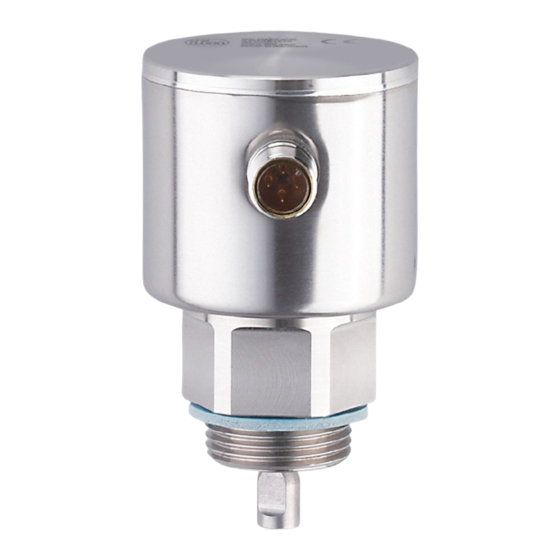
Electronic level sensor
Brand: IFM
|
Category: Accessories
|
Size: 0 MB
Table of Contents
Advertisement

IFM LX Series Operating Instructions Manual (25 pages)
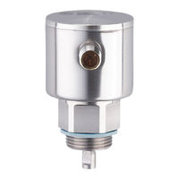
Electronic level sensor
Brand: IFM
|
Category: Measuring Instruments
|
Size: 0 MB
Table of Contents
Advertisement