Sign In
Upload
Manuals
Brands
IEN Manuals
Controller
P100C-SX
IEN P100C-SX Manuals
Manuals and User Guides for IEN P100C-SX. We have
1
IEN P100C-SX manual available for free PDF download: Instruction Manual
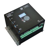
IEN P100C-SX Instruction Manual (248 pages)
AUTOMATIC VOLTAGE REGULATOR
Brand:
IEN
| Category:
Controller
| Size: 10 MB
Table of Contents
Table of Contents
5
Introduction
8
Getting Started
9
Safety Instructions
9
Communication & System Requirements
9
Software Installation
10
Demo Mode
12
Mounting & Wiring
13
Box Overview
13
Environmental Requirements
14
Physical Mounting
15
Grounding
15
Connecting Ios
15
Communications
16
Faceplate Keypad & Display
16
First Connection
21
Introduction
22
P100C-Sx Features
22
Overview
22
Modular Design
24
Supply Module
25
Main Board
25
Extension Board
25
GCU Module
26
MSP Module
29
Local Controller
30
Typical Applications
31
Wiring Diagram for P100C-Sx
32
Overview
32
Internal Thyristor Bridge - GCU
33
Internal Transistor - IGBT
34
External Thyristor Bridge - GCU
35
Interfaces and Terminal Strips
37
Communication
37
Electronics Supply
41
Isolated DC Analog Input
43
Isolated AC Analog Input
44
Analog Inputs and Outputs (4-20Ma)
45
Binary Outputs (Dry Contact)
46
Binary Inputs (Opto-Isolated)
49
Generator Voltage Measurement
52
Generator Current Measurement
53
Internal Power Converter
54
GCU - Firing Pulses
56
GCU - Status Leds
57
External LEM
58
Service Analog Outputs
59
Dimensions
60
Software Description
64
Introduction
64
Automatic Regulation Loop
64
Input Limitation
66
Soft Start
67
Automatic Regulation Set Point
68
Manual Regulation Loop
69
Manual Regulation Set Point
70
Tracking
70
Active Channel
70
Not Active Channel
71
Test Mode & Test Set Point
71
Limiters
72
Temperature Correction of Generator Capability Curve
73
P/Q Limiter
73
Minimal Exciter Field Current Limiter
75
Volts-Per-Hertz Limiter
76
Field Current Limiter
79
Stator Current Limiter & Reactive Power Regulator
81
Stator Current Limiter
81
Reactive Power Regulator
82
Power System Stabilizer
85
Output Linearization
86
Com Monitor
89
Options
89
Measurements
90
Analog Inputs
93
Analog Outputs
94
Miscellaneous
95
Network
95
Time
97
Other Buttons
98
Outputs Logic
99
Inputs Logic
101
Function 1: AVR on (Start)
103
Function 2: Power Converter Control
111
Function 3: Field Flashing Control
119
Function 4: ALARM Signal
124
Function 5: AVR off (Stop)
127
Function 6: Measurement Control
130
Function 7: Mode Control
134
Function 8: Setpoint
139
Function 9: Q,Q0,PF Regulator
143
Function 10: TRIP Signal
148
Function 11: Power Converter Temperature
151
Function 12: Power Supply Control
154
Function 13: Swap Channels
157
Function 14: Protections 1
160
Function 15: Fan Control
164
Function 16: Binary Inputs Control
167
Function 17: Power Converter 1 Diagnostic
169
Function 18: Power Converter 2 Diagnostic
173
Function 19: Power Converter 3 Diagnostic
177
Function 20: Power Converter 4 Diagnostic
181
Function 21: Current Distribution Control
185
Function 22: Rotor Temperature
187
Function 23: Voltage Matching
189
Function 24: Boosting
191
Function 25: Thyristor Conductance Detection
196
Function 26: Source Change over
198
Function 27: Loss of Field Protection
201
Function 28: Protections 2
204
Function 29: Protections 3
207
Function 31: Logic Developer
210
Function 32: Special Binary Extension
211
Oscilloscope
213
Recorder
214
Pss Tuning
215
PSS Settings Window
216
PSS Tools Window
218
Connecting Disturbance Signal
219
Generator Simulator
221
Settings
221
Running Simulation
223
Appendix
225
List of Events
225
List of Alarms
240
Advertisement
Advertisement
Related Products
IEN Categories
Controller
More IEN Manuals
Login
Sign In
OR
Sign in with Facebook
Sign in with Google
Upload manual
Upload from disk
Upload from URL