Sign In
Upload
Manuals
Brands
IEI Technology Manuals
PCI Card
WAFER-UTL4
IEI Technology WAFER-UTL4 Manuals
Manuals and User Guides for IEI Technology WAFER-UTL4. We have
1
IEI Technology WAFER-UTL4 manual available for free PDF download: User Manual
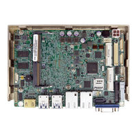
IEI Technology WAFER-UTL4 User Manual (134 pages)
3.5'' SBC with 6/7 Generation Intel Mobile Core i7/i5/i3 or Celeron SoC, DDR4 SO-DIMM, Triple Display, Dual GbE, PCIe Mini, SATA 6Gb/s, Usb 3.0, COM,HD Audio and RoHS
Brand:
IEI Technology
| Category:
PCI Card
| Size: 5.62 MB
Table of Contents
Table of Contents
5
1 Introduction
14
Introduction
15
Figure 1-1: WAFER-ULT3/ULT4
15
Model Variations
16
Features
16
Table 1-1: Model Variations
16
Connectors
17
Figure 1-2: Connectors (Front Side)
17
Figure 1-3: Connectors (Solder Side)
18
Dimensions
19
Figure 1-4: WAFER-ULT3/ULT4 Dimensions (MM)
19
Figure 1-5: Dimensions with Optional Heatsink (MM)
20
Data Flow
21
Figure 1-6: Data Flow Diagram
21
Technical Specifications
22
Table 1-2: WAFER-ULT3/ULT4 Specifications
23
2 Packing List
24
Anti-Static Precautions
25
Unpacking Precautions
25
Packing List
26
Optional Items
27
Table 2-1: Packing List
27
Table 2-2: Optional Items
27
3 Connectors
28
Peripheral Interface Connectors
29
WAFER-ULT3/ULT4 Layout
29
Figure 3-1: Peripheral Interface Connectors
29
Peripheral Interface Connectors
30
Table 3-1: Peripheral Interface Connectors
30
External Interface Panel Connectors
31
Internal Peripheral Connectors
31
Power Connector
31
Table 3-2: External Peripheral Connectors
31
Figure 3-2: Power Connector Location
32
Table 3-3: Power Connector Pinouts
32
SATA Power Connector
33
Audio Connector
33
Figure 3-3: 5 V SATA Power Connector Location
33
Table 3-4: 5 V SATA Power Connector Pinouts
33
Battery Connector
34
Figure 3-4: Audio Connector Location
34
Table 3-5: Audio Connector Pinouts
34
CPU Fan Connector
35
Figure 3-5: Battery Connector Location
35
Table 3-6: Battery Connector Pinouts
35
Digital I/O Connector
36
Figure 3-6: CPU Fan Connector Location
36
Table 3-7: CPU Fan Connector Pinouts
36
Internal Displayport Connector
37
Figure 3-7: Digital I/O Connector Location
37
Table 3-8: Digital I/O Connector Pinouts
37
Figure 3-8: Internal Displayport Connector Location
38
Table 3-9: Internal Displayport Connector Pinouts
38
LVDS Backlight Control Connector
39
Figure 3-9: LVDS Backlight Control Connector Location
39
Table 3-10: LVDS Backlight Control Connector Pinouts
39
LVDS Connector
40
Figure 3-10: LVDS Connector Location
40
Pcie Mini Card Slot (with Msat Support)
41
Figure 3-11: Pcie Mini Card Slot (with Msata Support) Location
41
Table 3-11: LVDS Connector Pinouts
41
Table 3-12: Pcie Mini Card Slot (with Msata Support) Pinouts
42
Pcie Mini Card Slot (with SIM Card Socket)
43
Figure 3-12: Pcie Mini Card Slot (with SIM Card Socket) Location
43
Power and HDD LED Connector
44
Table 3-13: Pcie Mini Card Slot (with SIM Card Socket) Pinouts
44
Power Button Connector
45
Figure 3-13: Power and HDD LED Connector Location
45
Table 3-14: Power and HDD LED Connector Pinouts
45
Reset Button Connector
46
Figure 3-14: Power Button Connector Location
46
Figure 3-15: Reset Button Connector Location
46
Table 3-15: Power Button Connector Pinouts
46
RS-232/422/485 Serial Port Connectors
47
Figure 3-16: RS-232 Serial Port Connector Locations
47
Table 3-16: Reset Button Connector Pinouts
47
Table 3-17: RS-232/422/485 Serial Port Connector Pinouts
48
Table 3-18: DB-9 RS-232/422/485 Pinouts
48
SATA 6Gb/S Connector
49
Figure 3-17: SATA 6Gb/S Connector Location
49
Table 3-19: SATA 6Gb/S Drive Connector Pinouts
49
SIM Card Slot
50
Figure 3-18: SIM Card Slot Location
50
Smbus Connector
51
Figure 3-19: Smbus Connector Location
51
Table 3-20: Smbus Connector Pinouts
51
SO-DIMM Slot
52
Figure 3-20: SO-DIMM Slot Location
52
SPI Flash Connector
53
Figure 3-21: SPI Flash Connector Location
53
Table 3-21: SPI Flash Connector Pinouts
53
USB 2.0 Connector
54
Figure 3-22: USB 2.0 Connector Location
54
Table 3-22: USB 2.0 Connector Pinouts
54
External Interface Connectors
55
Gbe Connectors
55
Figure 3-23: External Interface Connectors
55
Figure 3-24: LAN Connector
55
HDMI Connector
56
Figure 3-25: HDMI Connector Pinout Locations
56
Table 3-23: LAN Pinouts
56
Table 3-24: HDMI Connector Pinouts
56
USB 3.0 Ports
57
Figure 3-26: USB 3.0 Port Pinout Locations
57
Table 3-25: USB 3.0 Port Pinouts
57
VGA Connector
58
Figure 3-27: VGA Connector
58
Table 3-26: VGA Connector Pinouts
58
4 Installation
59
Anti-Static Precautions
60
Installation Considerations
60
So-DIMM Installation
62
Pcie Mini Card Installation
62
Figure 4-1: SO-DIMM Installation
62
Figure 4-2: Removing the Retention Screw
63
Figure 4-3: Inserting the Pcie Mini Card into the Slot at an Angle
63
Sim Card Installation
64
Figure 4-4: Securing the Pcie Mini Card
64
Figure 4-5: Unlock SIM Card Slot Cover
65
Figure 4-6: SIM Card Installation
65
System Configuration
66
AT/ATX Power Mode Selection
66
Figure 4-7: Lock SIM Card Slot Cover
66
Figure 4-8: AT/ATX Power Mode Switch Location
66
Table 4-1: AT/ATX Power Mode Switch Settings
66
Clear CMOS Button
67
Flash Descriptor Security Override Jumper
67
Figure 4-9: Clear CMOS Button Location
67
Table 4-2: Flash Descriptor Security Override Jumper Settings
67
LVDS Panel Type Selection
68
Figure 4-10: Flash Descriptor Security Override Jumper Location
68
Figure 4-11: LVDS Panel Type Selection Switch Location
69
Table 4-3: LVDS Panel Type Selection
69
LVDS Voltage Selection
70
Figure 4-12: LVDS Voltage Selection Jumper Location
70
Table 4-4: LVDS Voltage Selection Jumper Settings
70
Serial Port Mode Selection Switch
71
Figure 4-13: Serial Port Mode Selection Switch Location
71
Table 4-5: Signal Mode Settings for Serial Port 1
71
Table 4-6: Signal Mode Settings for Serial Port 2
71
Vga/Idp Selection Switch
72
Figure 4-14: Vga/Idp Selection Switch Location
72
Table 4-7: Vga/Idp Selection Switch Settings
72
Chassis Installation
73
Heat Sink Enclosure
73
Figure 4-15: Heat Sink Retention Screws
73
Motherboard Installation
74
Figure 4-16: Motherboard Installation Example
74
Internal Peripheral Device Connections
75
AT/ATX Power Connection
75
Figure 4-17: Power Cable to Motherboard Connection
75
Figure 4-18: Connect Power Cable to Power Supply
76
SATA Drive Connection
77
Figure 4-19: SATA Drive Cable Connection
77
Adding USB 3.0 Drivers to a Windows 7 Installation Image (6Th Generation Intel® Mobile ULT On-Board Soc Only)
78
Figure 4-20: Windows 7 USB 3.0 Creator Utility
79
Figure 4-21: Update Process Is Complete
79
Intel ® Amt Setup Procedure
80
Driver Installation
81
5 Bios
82
Introduction
83
Starting Setup
83
Using Setup
83
Getting Help
84
Unable to Reboot after Configuration Changes
84
BIOS Menu Bar
84
Table 5-1: BIOS Navigation Keys
84
Main
85
BIOS Menu 1: Main
85
Advanced
86
BIOS Menu 2: Advanced
86
CPU Configuration
87
BIOS Menu 3: CPU Configuration
87
PCH-FW Configuration
89
BIOS Menu 4: PCH-FW Configuration
89
ACPI Settings
90
BIOS Menu 5: ACPI Settings
90
F81866 Super IO Configuration
91
Serial Port N Configuration
91
BIOS Menu 6: F81866 Super IO Configuration
91
BIOS Menu 7: Serial Port N Configuration Menu
91
Iwdd H/W Monitor
94
BIOS Menu 8: Iwdd H/W Monitor
94
Smart Fan Mode Configuration
95
BIOS Menu 9: Smart Fan Mode Configuration
95
RTC Wake Settings
96
BIOS Menu 10: RTC Wake Settings
96
Serial Port Console Redirection
97
BIOS Menu 11: Serial Port Console Redirection
97
Console Redirection Settings
98
BIOS Menu 12: Console Redirection Settings
98
Legacy Console Redirection Settings
100
BIOS Menu 13: Legacy Console Redirection Settings
100
USB Configuration
101
BIOS Menu 14: USB Configuration
101
Iei Feature
102
BIOS Menu 15: Iei Feature
102
Chipset
103
System Agent (SA) Configuration
103
BIOS Menu 16: Chipset
103
BIOS Menu 17: System Agent (SA) Configuration
103
Memory Configuration
104
BIOS Menu 18: Memory Configuration
104
Graphics Configuration
105
BIOS Menu 19: Graphics Configuration
105
BIOS Menu 20: LCD Control
107
PCH-IO Configuration
108
BIOS Menu 21: PCH-IO Configuration
108
PCI Express Configuration
109
BIOS Menu 22: PCI Express Configuration
109
BIOS Menu 23: M_PCIE2 Configuration Menu
110
SATA Configuration
111
BIOS Menu 24: SATA Configuration
111
HD Audio Configuration
112
BIOS Menu 25: PCH Azalia Configuration
112
Security
113
BIOS Menu 26: Security
113
Boot
114
BIOS Menu 27: Boot
114
Save & Exit
116
BIOS Menu 28: Save & Exit
116
A Regulatory Compliance
117
BBIOS Options
119
C Terminology
122
D Digital I/O Interface
126
Introduction
127
D.1 I Ntroduction
127
Assembly Language Sample 1
128
Assembly Language Sample
128
D.2 a Ssembly L Anguage S Ample 1
128
E Watchdog Timer
129
F Hazardous Materials Disclosure
132
Advertisement
Advertisement
Related Products
IEI Technology WAFER-UTL3
IEI Technology WAFER-US15WP2
IEI Technology WAFER-ULT-i1
IEI Technology WAFER-ULT2-i1
IEI Technology WAFER-ULT5
IEI Technology WAFER-ULT4
IEI Technology WAFER-ULT4-i5
IEI Technology WAFER-ULT4-i3
IEI Technology WAFER-ULT3-i7
IEI Technology WAFER-ULT3-i5
IEI Technology Categories
Motherboard
Touch Panel
Computer Hardware
Single board computers
Desktop
More IEI Technology Manuals
Login
Sign In
OR
Sign in with Facebook
Sign in with Google
Upload manual
Upload from disk
Upload from URL