Sign In
Upload
Manuals
Brands
IEI Technology Manuals
Motherboard
WAFER-PV-N4552-R11
IEI Technology WAFER-PV-N4552-R11 Manuals
Manuals and User Guides for IEI Technology WAFER-PV-N4552-R11. We have
1
IEI Technology WAFER-PV-N4552-R11 manual available for free PDF download: User Manual
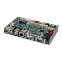
IEI Technology WAFER-PV-N4552-R11 User Manual (116 pages)
Brand:
IEI Technology
| Category:
Motherboard
| Size: 5.97 MB
Table of Contents
Table of Contents
4
Introduction
13
Introduction
14
Benefits
14
Figure 1-1: WAFER-PV-D5252/D4252/N4552
14
Features
15
Connectors
15
Figure 1-2: Connectors
15
Dimensions
16
Figure 1-3: Dimensions Without Heatsink (MM)
16
Figure 1-4: Dimensions with Heatsink (MM)
17
Data Flow
18
Figure 1-5: Data Flow Diagram
18
Technical Specifications
19
Table 1-1: Technical Specifications
20
Packing List
21
Anti-Static Precautions
22
Unpacking Precautions
22
Packing List
23
Optional Items
24
Table 2-1: Packing List
24
Table 2-2: Optional Items
24
Connector Pinouts
25
Peripheral Interface Connectors
26
Layout
26
Figure 3-1: Connector and Jumper Locations
26
Peripheral Interface Connectors
27
External Interface Panel Connectors
28
Internal Peripheral Connectors
28
ATX Power Connector
28
Table 3-1: Peripheral Interface Connectors
28
Table 3-2: Rear Panel Connectors
28
Audio Connector
29
Figure 3-2: ATX Power Connector Location
29
Figure 3-3: Audio Connector Location
29
Table 3-3: ATX Power Connector Pinouts
29
Battery Connector
30
Figure 3-4: Battery Connector Location
30
Table 3-4: Audio Connector Pinouts
30
Table 3-5: Battery Connector Pinouts
30
Compactflash® Slot
31
Figure 3-5: Compactflash® Slot Location
31
Digital I/O Connector
32
Table 3-6: Compactflash® Slot Pinouts
32
Fan Connectors
33
Figure 3-6: Digital I/O Connector Location
33
Table 3-7: Digital I/O Connector Pinouts
33
Keyboard/Mouse Connector
34
Figure 3-7: Fan Connector Locations
34
Table 3-8: Fan Connector Pinouts
34
LED and +5 V Power Output Connector
35
Figure 3-8: Keyboard/Mouse Connector Location
35
Table 3-9: Keyboard/Mouse Connector Pinouts
35
LVDS Connector
36
Figure 3-9: LED and +5 V Power Output Connector Location
36
Table 3-10: LED and +5 V Power Output Connector Pinouts
36
LVDS Backlight Connector
37
Figure 3-10: LVDS Connector Location
37
Table 3-11: LVDS Connector Pinouts
37
Pcie Mini Card Slot
38
Figure 3-11: Backlight Inverter Connector
38
Table 3-12: Backlight Inverter Connector
38
Figure 3-12: Pcie Mini Card Slot Location
39
Power Button Connector
40
Reset Button Connector
40
Figure 3-13: Power Button Connector Location
40
Table 3-13: Pcie Mini Card Slot Pinouts
40
Table 3-14: Power Button Connector Pinouts
40
RS-232/422/485 Serial Port Connector (COM6)
41
Figure 3-14: Reset Button Connector Location
41
Figure 3-15: RS-232/422/485 Serial Port Connector Location
41
Table 3-15: Reset Button Connector Pinouts
41
Serial Port Connector (COM2~COM5)
42
Figure 3-16: RS-232 Serial Port Connector Location
42
Table 3-16: RS-232/422/485 Serial Port Connector Pinouts
42
SATA Drive Connectors
43
Figure 3-17: SATA Drive Connector Location
43
Table 3-17: Serial Port Connector Pinouts
43
SATA Power Connectors
44
Figure 3-18: SATA Power Connector Locations
44
Table 3-18: SATA Drive Connector Pinouts
44
Table 3-19: SATA Power Connector Pinouts
44
Smbus Connector
45
SO-DIMM Connector
45
Figure 3-19: Smbus Connector Location
45
Table 3-20: Smbus Connector Pinouts
45
SPI Flash Connector
46
Figure 3-20: SO-DIMM Connector Location
46
Figure 3-21: SPI Flash Connector Location
46
Table 3-21: SPI Flash Connector Pinouts
46
USB Connectors
47
Figure 3-22: USB Connector Location
47
Table 3-22: USB Port Connector Pinouts
47
External Interface Connectors
48
Ethernet Connectors
48
Figure 3-23: External Interface Connectors
48
Table 3-23: Ethernet Connector Pinouts
48
Serial Port Connector
49
Figure 3-24: Ethernet Connector
49
Table 3-24: RJ-45 Ethernet Connector Leds
49
Table 3-25: Serial Port Pinouts
49
USB Ports
50
VGA Connector
50
Figure 3-25: Serial Port Pinout Locations
50
Table 3-26: USB Connector Pinouts
50
Figure 3-26: VGA Connector
51
Table 3-27: VGA Connector Pinouts
51
Installation
52
Anti-Static Precautions
53
Installation Considerations
54
So-DIMM Installation
55
Figure 4-1: SO-DIMM Installation
55
Compactflash® Installation
56
Figure 4-2: Compactflash® Card Installation
56
Jumper Settings
57
AT/ATX Mode Selection
57
Table 4-1: Jumpers
57
Clear CMOS Jumper
58
Figure 4-3: AT/ATX Mode Selection Jumper Location
58
Table 4-2: AT/ATX Mode Selection
58
LVDS Voltage Selection
59
Figure 4-4: Clear CMOS Jumper Location
59
Table 4-3: Clear CMOS Jumper Settings
59
LVDS Resolution Selection
60
Figure 4-5: LVDS Voltage Selection Jumper Location
60
Table 4-4: LVDS Voltage Selection
60
Table 4-5: LVDS Resolution Selection
60
Compactflash® Master/Slave Selection
61
Figure 4-6: LVDS Resolution Selection Jumper Location
61
Table 4-6: Compactflash® Master/Slave Selection
61
COM6 RS-232/422/485 Selection
62
Figure 4-7: Compactflash® Master/Slave Selection Jumper Location
62
Figure 4-8: COM6 RS-232/422/485 Selection Jumper Location
62
Table 4-7: COM6 RS-232/422/485 Selection
62
COM 1 Pin 9 Setting Jumper
63
Figure 4-9: COM 1 Pin 9 Setting Jumper Location
63
Table 4-8: COM 1 Pin 9 Setting Jumper Settings
63
Chassis Installation
64
Airflow
64
Motherboard Installation
64
Internal Peripheral Device Connections
64
AT Power Connection
64
Audio Kit Installation
65
Figure 4-10: Power Cable to Motherboard Connection
65
Figure 4-11: Audio Kit Cable Connection
66
Keyboard/Mouse Connector
67
Figure 4-12: Connect Power Cable to Power Supply
67
Figure 4-13: Keyboard/Mouse Y-Cable Connection
68
Four Serial Port Connector
69
Figure 4-14: Four Serial Port Connector
69
Software Installation
70
Figure 4-15: Serial Device Connector
70
Figure 4-16: Introduction Screen
71
Figure 4-17: Available Drivers
71
Bios
72
Introduction
73
Starting Setup
73
Using Setup
73
Getting Help
74
Unable to Reboot after Configuration Changes
74
BIOS Menu Bar
74
Table 5-1: BIOS Navigation Keys
74
Main
75
BIOS Menu 1: Main
75
Advanced
76
BIOS Menu 2: Advanced
76
ACPI Configuration
77
BIOS Menu 3: ACPI Configuration
77
RTC Wake Settings
78
BIOS Menu 4: RTC Wake Settings
78
CPU Configuration
79
BIOS Menu 5: CPU Configuration
79
IDE Configuration
80
BIOS Menu 6: IDE Configuration
80
USB Configuration
82
BIOS Menu 7: USB Configuration
82
Super IO Configuration
83
BIOS Menu 8: Super IO Configuration
83
Serial Port N Configuration
84
BIOS Menu 9: Serial Port N Configuration Menu
84
H/W Monitor
89
BIOS Menu 10: Hardware Health Configuration
89
Serial Port Console Redirection
90
BIOS Menu 11: Serial Port Console Redirection
91
IEI Feature
92
BIOS Menu 12: IEI Feature
92
Chipset
93
BIOS Menu 13: Chipset
93
Host Bridge
94
BIOS Menu 14:Host Bridge Configuration
94
South Bridge
95
BIOS Menu 15:Southbridge Chipset Configuration
95
Intel IGD SWSCI Opregion
97
BIOS Menu 16: Intel IGD SWSCI Opregion
97
Boot
99
BIOS Menu 17: Boot
99
Security
101
Exit
101
BIOS Menu 18: Security
101
BIOS Menu 19:Exit
102
ABIOS Options
103
B Terminology
106
C Digital I/O Interface
110
Introduction
111
Assembly Language Sample
112
Assembly Language Sample 2
112
D Hazardous Materials Disclosure
113
Hazardous Materials Disclosure Table for IPB Products Certified as Rohs Compliant under 2002/95/EC Without Mercury
114
Advertisement
Advertisement
Related Products
IEI Technology WAFER-PV-N4551
IEI Technology WAFER-PV-D4251
IEI Technology WAFER-PV-D4252
IEI Technology WAFER-PV-N4552
IEI Technology WAFER-PV-D5252
IEI Technology WAFER-PV-D4253
IEI Technology WAFER-PV-D5253
IEI Technology WAFER-PV-N4553
IEI Technology WAFER-PV-D5251
IEI Technology Wafer-CX700m
IEI Technology Categories
Motherboard
Touch Panel
Computer Hardware
Single board computers
Desktop
More IEI Technology Manuals
Login
Sign In
OR
Sign in with Facebook
Sign in with Google
Upload manual
Upload from disk
Upload from URL