Sign In
Upload
Manuals
Brands
IEI Technology Manuals
Touch Panel
PPC-FxxA-H81
IEI Technology PPC-FxxA-H81 Manuals
Manuals and User Guides for IEI Technology PPC-FxxA-H81. We have
1
IEI Technology PPC-FxxA-H81 manual available for free PDF download: User Manual
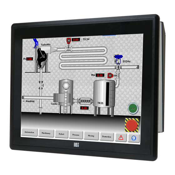
IEI Technology PPC-FxxA-H81 User Manual (176 pages)
Industrial Panel PC
Brand:
IEI Technology
| Category:
Touch Panel
| Size: 12 MB
Table of Contents
Table of Contents
4
Introduction
14
Overview
15
Figure 1-1: PPC-Fxxa-H81 Panel PC
15
Model Variations
16
Features
17
Table 1-1: Model Variations
17
M Odel V Ariations 1.3 F Eatures
17
Front Panel
18
Rear Panel
18
Figure 1-2: Front View
18
Bottom Panel
19
Figure 1-3: PPC-F15A-H81 Rear View
19
Figure 1-4: Bottom View
20
Internal Overview
21
Figure 1-5: PPC-F15A-H81 Internal Components
21
Figure 1-6: PPC-F22A-H81 Internal Components
21
Dimensions
22
D IMENSIONS 1.8.1 PPC-F15A-H81 Dimensions
22
Figure 1-7: PPC-F15A-H81 Dimensions (MM)
22
PPC-F15A-H81 Dimensions
22
Figure 1-8: PPC-F17A-H81 Dimensions (MM)
23
PPC-F17A-H81 Dimensions
23
Figure 1-9: PPC-F22A-H81 Dimensions (MM)
24
PPC-F22A-H81 Dimensions
24
Figure 1-10: PPC-F24A-H81 Dimensions (MM)
25
PPC-F24A-H81 Dimensions
25
Specifications
26
Table 1-2: System Specifications
27
Unpacking
28
Unpacking
29
Packing List
30
Table 2-1: Packing List
30
Optional Items
31
Table 2-2: Optional Items
31
Installation
32
Anti-Static Precautions
33
Installation Precautions
33
Preinstalled Components
34
Installation and Configuration Steps
34
Removing the
35
Figure 3-1: PPC-F15A-H81 Back Cover Retention Screws
35
Hdd Installation
36
Figure 3-2: PPC-F15A/F17A-H81 HDD Bracket Retention Screws
36
PPC-F15A/F17A-H81 HDD Installation
36
Figure 3-3: HDD Retention Screws
37
Figure 3-4: Replacing the PPC-F15A/F17A-H81 HDD Bracket
37
Figure 3-5: PPC-F22A/F24A-H81 HDD Bracket Retention Screws
38
PPC-F22A/F24A-H81 2.5"HDD Installation
38
Figure 3-6: Connecting the Hard Drive to the HDD Bracket
39
Figure 3-7: 2.5" HDD Retention Screws
39
Figure 3-8: Replacing the PPC-F22A/F24A-H81 HDD Bracket
40
PPC-F22A/F24A-H81 3.5"HDD Installation
40
Figure 3-10: 3.5" HDD Retention Screws
41
Figure 3-9: Connecting the Hard Drive to the HDD Bracket
41
Msata Module Installation
42
Figure 3-11: Replacing the PPC-F22A/F24A-H81 HDD Bracket
42
Figure 3-12: Pcie Mini Card Slot Which Supports Msata
43
Figure 3-13: Removing the Retention Screws
43
Figure 3-14: Inserting the Pcie Mini Card into the Slot at an Angle
44
Iris-2400 Module Installation
45
Figure 3-15: Securing the Pcie Mini Card
45
Figure 3-16: Iris-2400 Module Slot
46
Figure 3-17: Iris-2400 Module Installation
46
At/Atx Mode Selection
47
Mounting the System
47
Figure 3-18: AT/ATX Mode Selection
47
Figure 3-19: Wall-Mounting Bracket
48
Wall Mounting
48
Figure 3-20: Mount the Chassis
49
Figure 3-21: Secure the Chassis
50
Panel Mounting
50
Figure 3-22: PPC-F15A-H81 Mounting Bracket Installation
51
Figure 3-23: PPC-F15A-H81 Panel Cutout Dimensions
51
Figure 3-24: PPC-F17A-H81 Panel Cutout Dimensions
52
Figure 3-25: PPC-F22A-H81 Panel Cutout Dimensions
52
Figure 3-26: PPC-F24A-H81 Panel Cutout Dimensions
53
Figure 3-27: Tighten the Mounting Clamp Screws
54
Rack and Cabinet Installation
54
Figure 3-28: the Rack/Cabinet Bracket
55
Figure 3-29: Secure the Rack/Cabinet Bracket
56
Arm Mounting
57
Figure 3-30: Install into a Rack/Cabinet
57
Figure 3-31: Arm Mounting Retention Screw Holes
58
Stand Mounting
58
External Peripheral Device Connection
59
Audio Device Connection
59
Figure 3-32: Stand Mounting Retention Screw Holes
59
Figure 3-33: Audio Connector
60
Figure 3-34: HDMI Connection
61
HDMI Display Device Connection
61
Figure 3-35: LAN Connection
62
LAN Connection
62
Serial Device Connection
62
Figure 3-36: RS-232 Serial Device Connector
63
USB Device Connection
63
Figure 3-37: USB Device Connection
64
VGA Connector Connection
64
Reset the System
65
Figure 3-38: VGA Connector
65
Figure 3-39: Reset Button Location
65
Clear Cmos
66
Usb Power Selection
66
Figure 3-40: Clear CMOS Button Location
66
Table 3-1: BIOS Options and Configured USB Ports
66
Table 3-2: USB Power Source Setup
66
Ipmi Setup Procedure
67
Managed System Hardware Setup
67
Using the IEI Iman Web GUI
67
Figure 3-41: IEI Iman Web Address
68
Figure 3-42: IEI Iman Web GUI
68
System Maintenance
69
System Maintenance Introduction
70
Motherboard Replacement
70
Back Cover Removal
70
So-DIMM Replacement
71
Figure 4-1: SO-DIMM Module Locations
71
System Cooling Fan Replacement
72
Figure 4-2: SO-DIMM Module Installation
72
Remove the Old System Cooling Fans
72
Figure 4-3: System Cooling Fans Motherboard Connectors
73
Figure 4-4: System Cooling Fan Retention Screws
73
Install the New System Cooling Fans
73
Bios Setup
75
Introduction
76
Starting Setup
76
Using Setup
76
BIOS Menu Bar
77
Getting Help
77
Table 5-1: BIOS Navigation Keys
77
Unable to Reboot after Configuration Changes
77
Main
79
Advanced
80
System Date [XX/XX/XX]
80
System Time [XX:XX:XX]
80
ACPI Settings
81
RTC Wake Settings
82
ACPI Sleep State [S1 Only (CPU Stop Clock)]
82
Wake System with Fixed Time [Disabled]
83
CPU Configuration
84
Active Processor Cores [All]
85
Intel Virtualization Technology [Disabled]
85
SATA Configuration
86
EIST [Enabled]
86
SATA Controller(S) [Enabled]
86
USB Configuration
87
SATA Mode Selection [IDE]
87
USB Devices
87
Legacy USB Support [Enabled]
87
F81866 Super IO Configuration
88
Serial Port N Configuration
89
Serial Port [Enabled]
89
Change Settings [Auto]
89
Serial Port [Enabled]
90
Change Settings [Auto]
90
Serial Port [Enabled]
91
Change Settings [Auto]
91
Change Settings [Auto]
92
Serial Port [Enabled]
92
Iwdd H/W Monitor
93
Device Mode [Normal]
93
PC Health Status
94
Console Redirection Settings
95
Serial Port Console Redirection
95
Console Redirection [Disabled]
95
Terminal Type [ANSI]
96
Bits Per Second [115200]
96
Data Bits [8]
97
Parity [None]
97
Stop Bits [1]
97
Iei Feature
98
Auto Recovery Function [Disabled]
98
Chipset
99
PCH-IO Configuration
100
Restore AC Power Loss [Last State]
100
Power Saving Function(ERP) [Disabled]
100
Table 5-2: BIOS Options and Configured USB Ports
101
USB SW1 Power [+5V DUAL]
101
USB SW2 Power [+5V DUAL]
101
PCI Express Configuration
102
PCH Azalia Configuration
103
Pcie Speed [Auto]
103
Detect Non-Compliance Device [Disbled]
103
Azalia (HD Audio) [Enabled]
104
System Agent (SA) Configuration
105
VT-D [Disabled]
105
Graphics Configuration
106
Primary Display [Auto]
106
DVMT Pre-Allocated [256M]
106
DVMT Total Gfx Mem [MAX]
107
Memory Configuration
108
Primary IGFX Boot Display [VBIOS Default]
108
Boot
109
Bootup Numlock State [On]
109
Quiet Boot [Enabled]
110
Option ROM Messages [Force BIOS]
110
Launch PXE Oprom [Disabled]
110
UEFI Boot [Disabled]
110
Security
111
Save & Exit
111
Administrator Password
111
User Password
111
Save Changes and Reset
112
Discard Changes and Reset
112
Restore Defaults
112
Save as User Defaults
112
Restore User Defaults
112
Driver Installation
113
Available Software Drivers
114
Starting the Driver Program
114
Chipset Driver Installation
115
Figure 6-1: Drivers
115
Figure 6-2: Chipset Driver Welcome Screen
116
Figure 6-3: Chipset Driver License Agreement
117
Figure 6-4: Chipset Driver Read Me File
117
Figure 6-5: Chipset Driver Setup Operations
118
Vga Driver Installation
119
Figure 6-6: Chipset Driver Installation Finish Screen
119
Figure 6-7: VGA Driver README FILE
120
Figure 6-8: VGA Driver Screen
120
Figure 6-9: VGA Driver Welcome Screen
121
Figure 6-10: VGA Driver License Agreement
121
Figure 6-11: VGA Driver Readme File Information
122
Figure 6-12: VGA Driver Setup Progress
122
Audio Driver Installation
123
Figure 6-13: VGA Driver Installation Finish Screen
123
Figure 6-14: Audio Driver Welcome Screen
124
Figure 6-15: Audio Driver Installation
124
Lan Driver Installation
125
Figure 6-16: Audio Driver Installation Complete
125
Figure 6-17: LAN Driver Welcome Screen
126
Figure 6-18: LAN Driver License Agreement
126
Figure 6-19: LAN Driver Setup Options
127
Figure 6-20: LAN Driver Installation
128
Figure 6-21: LAN Driver Installation Complete
128
Usb 3.0 Driver Installation
129
Figure 6-22: USB 3.0 Driver Welcome Screen
129
Figure 6-23: USB 3.0 Driver License Agreement
130
Figure 6-24: USB 3.0 Driver Read Me File
131
Figure 6-25: USB 3.0 Driver Setup Operations
131
Resistive Type Touchscreen Driver Installation
132
Figure 6-26: USB 3.0 Driver Installation Finish Screen
132
Figure 6-27: Welcome Screen
133
Figure 6-28: Touchscreen Driver License Agreement
133
Figure 6-29: Choose Destination Folder
134
Figure 6-30: Setup Status
134
Calibrating the Resistive Type Touchscreen
135
Figure 6-31: Select Touch Features
135
Figure 6-32: Touchscreen Driver Installation Finish Screen
135
Figure 6-33: Select Control Panel
136
Figure 6-34: Touchscreen Control Panel
136
Figure 6-35: Select Calibration Type
137
Figure 6-36: Calibration Window
137
Keypad Ap Installation
138
Figure 6-37: Keypad AP Welcome Screen
138
Figure 6-38: Select Installation Folder
139
Figure 6-39: Confirm Installation
139
Figure 6-40: Keypad AP Installation Complete
140
Figure 6-41: Keypad AP Installation Complete
140
Figure 6-42: Keypad AP
141
Interface Connectors
142
Peripheral Interface Connectors
143
Figure 7-1: Main Board Layout Diagram (Front Side)
143
Internal Peripheral Connectors
144
Figure 7-2: Main Board Layout Diagram (Solder Side)
144
Table 7-1: Peripheral Interface Connectors
145
ATX Power Connector (ATX1)
146
Power Source Connector (CPU12V1)
146
Table 7-2: +12V Power Source Connector ( CPU12V1) Pinouts
146
Table 7-3: ATX Power Connector (ATX1) Pinouts
146
Debug Port (DBG_PORT1)
147
DIO Connector (DIO1)
147
Table 7-4: Debug Port (DBG_PORT1) Pinouts
147
Table 7-5: DIO Connector (DIO1) Pinouts
147
EC Debug Port (LPT_DB1)
148
Fan Connectors (CPU_FAN1/SYS_FAN1/SYS_FAN2)
148
Table 7-6: EC Debug Port (LPT_DB1) Pinouts
148
Table 7-7: Fan Connector Pinouts
148
Front Panel Connector (F_PANEL1)
149
I 2 C Connector (CN5)
149
IPMI Active LED Connector (LEDCN1)
149
Table 7-10: IPMI Active LED Connector (LEDCN1) Pinouts
149
Table 7-8: Front Panel Connector (F_PANEL1) Pinouts
149
Table 7-9: I 2 C Connector (CN5) Pinouts
149
Keyboard and Mouse Connector (KBMS1)
150
Keypad Connector (HOTKEY_CN1)
150
LAN Active LED Connectors (LED_LAN1/LED_LAN2)
150
Table 7-11: Keyboard and Mouse Connector (KBMS1) Pinouts
150
Table 7-12: Keypad Connector (HOTKEY_CN1) Pinouts
150
Table 7-13: LAN Active LED Connectors (LED_LAN1/LED_LAN2) Pinouts
150
LVDS Connector (LVDS1)
151
Panel Power Supply Connector (INVERTER1)
151
Table 7-14: LVDS Connector (LVDS1) Pinouts
151
Table 7-15: Panel Power Supply Connector (INVERTER1) Pinouts
151
Pcie Mini (MINI_PCIE1) and Msata (MSATA1) Card Slots
152
Table 7-16: Pcie Mini (MINI_PCIE1) and Msata (MSATA1) Card Pinouts
152
Resistive Touchscreen Connector (TOUCH1)
153
SATA 6Gb/S Connectors (S_ATA1/S_ATA2)
153
Table 7-17: Resistive Touchscreen Connector (TOUCH1) Pinouts
153
Table 7-18: SATA 6Gb/S Connectors (S_ATA1/S_ATA2) Pinouts
153
SATA Power Connectors (SATA_PWR1/SATA_PWR2)
154
Smbus Connector (CN1)
154
SPI Flash Connector (JSPI1)
154
Table 7-19: SATA Power Connectors (SATA_PWR1/SATA_PWR2) Pinouts
154
Table 7-20: Smbus Connector (CN1) Pinouts
154
Table 7-21: SPI Flash Connector (JSPI1) Pinouts
154
SPI Flash (EC) Connector (JSPI2)
155
Table 7-22: SPI Flash (EC) Connector (JSPI2) Pinouts
155
Table 7-23: U3 Firmware Programming Connector (JP1) Pinouts
155
Table 7-24: USB 2.0 Connector (USB1) Pinouts
155
U3 Firmware Programming Connector (JP1)
155
USB 2.0 Connector (USB1)
155
External Interface Panel Connectors
156
HDMI Connector (HDMI1)
156
Table 7-25: Rear Panel Connectors
156
Gbe and USB 2.0 Connectors (LAN2_USB2)
157
Serial Ports (COM1/COM2, COM3/COM4)
157
Table 7-26: HDMI Connector (HDMI1) Pinouts
157
Table 7-27: RS-232 Serial Port Pinouts
157
Table 7-28: USB 2.0 Connector (USB_CON1) Pinouts
157
Table 7-29: RJ-45 Gbe Connector (LAN2_USB2) Pinouts
157
USB 2.0 Connectors (USB_CON1)
157
Gbe and USB 3.0 Connectors (LAN1_USB1)
158
Table 7-30: USB 2.0 Connector (LAN2_USB2) Pinouts
158
Table 7-31: RJ-45 Gbe Connector (LAN1_USB1) Pinouts
158
Table 7-32: USB 3.0 Connector (LAN1_USB1) Pinouts
158
RS-422/485 Serial Port and VGA Connector (COM5/VGA1)
159
Preconfigured Jumpers
159
Table 7-33: RS-422/485 Serial Port (COM5) Pinouts
159
Table 7-34: VGA Connector (VGA1) Pinouts
159
Flash Descriptor Security Override Jumper (J_FLASH1)
160
LVDS Panel Resolution Selection Switch (JLCD_SET1)
160
Table 7-35: Preconfigured Jumpers
160
Table 7-36: Flash Descriptor Security Override Jumper (J_FLASH1) Settings
160
Table 7-37: LVDS Panel Resolution Selection
160
Panel Voltage Selection Jumper (JLCD_PWR1)
161
Table 7-38: Panel Voltage Selection Jumper (JLCD_PWR1) Settings
161
Table 7-39: Touchscreen Selection Jumper (JTOUCH1) Settings
161
Touchscreen Selection Jumper (JTOUCH1)
161
A Bios Configuration Options
162
A.1 BIOS Configuration Options
163
A.1 Bios C Onfiguration O Ptions
163
Bios Configuration Options
163
B Safety Precautions
165
Safety Precautions
166
General Safety Precautions
166
Anti-Static Precautions
167
Product Disposal
167
Maintenance and Cleaning Precautions
168
B.2 M Aintenance and C Leaning P Recautions
168
Maintenance and Cleaning
168
Cleaning Tools
169
C Watchdog Timer
170
Example Program
172
D Hazardous Materials Disclosure
173
Hazardous Material Disclosure Table for IPB Products Certified as Rohs Compliant under 2002/95/EC Without Mercury
174
D.1 H Azardous M Aterial D Isclosure T Able for Ipb P Roducts C Ertified as R O Hs C Ompliant U Nder 2002/95/Ec W Ithout M Ercury
174
Advertisement
Advertisement
Related Products
IEI Technology PPC-F12B
IEI Technology PPC-F10B-BT
IEI Technology PPC-F15C-Q370-P/PC/25
IEI Technology PPC-F15C-Q370-i7/PC/25
IEI Technology PPC-FW15C-Q370-P/PC/25
IEI Technology PPC-F17C-Q370-i3/PC/25
IEI Technology PPC-FW19C-Q370-P/PC/25
IEI Technology PPC-FW22C-Q370-P/PC/25
IEI Technology PPC-F12B-BT
IEI Technology PPC-F19B-BT
IEI Technology Categories
Motherboard
Touch Panel
Computer Hardware
Single board computers
Desktop
More IEI Technology Manuals
Login
Sign In
OR
Sign in with Facebook
Sign in with Google
Upload manual
Upload from disk
Upload from URL