Sign In
Upload
Manuals
Brands
IEI Technology Manuals
Computer Hardware
IMBA-H420-R10
IEI Technology IMBA-H420-R10 Manuals
Manuals and User Guides for IEI Technology IMBA-H420-R10. We have
1
IEI Technology IMBA-H420-R10 manual available for free PDF download: User Manual
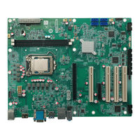
IEI Technology IMBA-H420-R10 User Manual (90 pages)
ATX motherboard supports 14nm LGA1200 Intel® 10th/ 11 th Generation Core™ i9/i7/i5/i3, Celeron® and Pentium® processor, DDR4, triple displays, 2.5 GbE LAN, USB 3.2, SATA 6Gb/s, HD Audio and RoHS
Brand:
IEI Technology
| Category:
Computer Hardware
| Size: 11 MB
Table of Contents
Table of Contents
5
Introduction
12
Ntroduction
13
Figure 1-1: IMBA-H420
13
Features
14
Connectors
15
Figure 1-2: Connectors
15
Dimensions
16
Figure 1-3: IMBA-H420 Dimensions (MM)
16
Data Flow
17
Figure 1-4: Data Flow Diagram
17
Technical Specifications
18
Table 1-1: IMBA-H420 Specifications
19
Packing List
20
Anti-Static Precautions
21
Unpacking Precautions
21
Packing List
22
Table 2-1: Packing List
22
Optional Items
23
Table 2-2: Optional Items
23
Connectors
24
Peripheral Interface Connectors
25
IMBA-H420 Layout
25
Figure 3-1: Peripheral Interface Connectors
25
Peripheral Interface Connectors
26
External Interface Panel Connectors
27
Table 3-1: Peripheral Interface Connectors
27
Table 3-2: Rear Panel Connectors
27
Internal Peripheral Connectors
28
CPU 12V Power Connector
28
Figure 3-2: ATX CPU 12V Power Connector Location
28
Table 3-3: ATX CPU 12V Power Connector Pinouts
28
Pcie Power Connector
29
Figure 3-3: Pcie Power Connector Location
29
Table 3-4: Pcie Power Connector Pinouts
29
ATX Power Connector
30
Figure 3-4: ATX Power Connector Location
30
Battery Connector
31
Table 3-5: ATX Power Connector Pinouts
31
Chassis Intrusion Connector
32
Figure 3-5: Battery Connector Location
32
Figure 3-6: Chassis Intrusion Connector Location
33
Table 3-6: Chassis Intrusion Connector Pinouts
33
Digital I/O Connector
34
Figure 3-7: Digital I/O Connector Location
34
Table 3-7: Digital I/O Connector Pinouts
34
EC Debug Connector
35
Figure 3-8: EC Debug Connector Location
35
Table 3-8: Digital I/O Connector Pinouts
35
Debug Connector
36
Figure 3-9: Debug Connector Location
36
Table 3-9: Debug Connector Pinouts
36
Fan Connector (CPU)
37
Figure 3-10: CPU Fan Connector Location
37
Table 3-10: CPU Fan Connector Pinouts
37
Fan Connectors (System)
38
Figure 3-11: System Fan Connector Locations
38
Table 3-11: System Fan Connector Pinouts
38
Front Panel Connector
39
Figure 3-12: Front Panel Location
39
Table 3-12: Front Panel Pinouts
39
Internal Audio Connector
40
Figure 3-13: Internal Audio Connector Location
40
Table 3-13: Internal Audio Connector Pinouts
40
I 2 C Connector
41
Figure 3-14: I 2 C Connector Location
41
Table 3-14: I2C Connector Pinouts
41
Smbus Connector
42
Figure 3-15: Smbus Connector Location
42
Table 3-15: Smbus Connector Pinouts
42
LAN Link LED Connector
43
Figure 3-16: JP2, JP3 Connector Locations
43
Table 3-16: JP2 Connector Pinouts
43
Table 3-17: JP3 Connector Pinouts
43
PCI Slots
44
Figure 3-17: PCI Slot Locations
44
PCIE X4 Slot
45
Figure 3-18: Pcie X4 Slot Locations
45
Pcie X16 Slot
46
Figure 3-19: Pcie X16 Slot Locations
46
Onboard Power Button
47
Figure 3-20: Power Button Location
47
DDR4 DIMM Sockets
48
Figure 3-21: DDR4 DIMM Location
48
SATA 6Gb/S Connectors
49
Figure 3-22: SATA 6Gb/S Connector Locations
49
Table 3-18: SATA 6Gb/S Connector Pinouts
49
Serial Port, RS-232
50
Figure 3-23: RS-232 Serial Port Connector Location
50
Table 3-19: RS-232 Serial Port Connector Pinouts
50
Serial Port, RS-232/422/485
51
Figure 3-24: RS-232/422/485 Connector Location
51
Table 3-20: RS-232/422/485 Connector Pinouts
51
Flash SPI ROM Connector
52
Figure 3-25: Flash SPI ROM Connector Location
52
Table 3-21: DB-9 RS-232/422/485 Pinouts
52
EC SPI Flash Connector
53
Figure 3-26: EC SPI Flash Connector Location
53
Table 3-22: Flash SPI ROM Connector Pinouts
53
Table 3-23: EC SPI Flash Connector Pinouts
53
Intennal DP++ Connector
54
Figure 3-27: DP++ Connector Location
54
Table 3-24: DP++ Connector Pinouts
54
Internal USB 2.0 Connectors
55
Figure 3-28: Internal USB 2.0 Connector Locations
55
Table 3-25: Internal USB 2.0 Connector Pinouts
55
VGA Firmware Refresh Connector
56
Figure 3-29: VGA Firmware Refresh Connector Location
56
Table 3-26: VGA Firmware Refresh Connector Pinouts
56
External Peripheral Interface Connector Panel
57
Figure 3-30: External Peripheral Interface Connector
57
External HD Audio Jack
58
Figure 3-31: Audio Connector
58
External Keyboard/Mouse and USB 2.0 Combo Connectors
59
Figure 3-32: PS2, USB 2.0 Connector
59
Table 3-27: USB 2.0 Port Pinouts
59
Table 3-28: PS2 Port Pinouts
59
External HDMI Combo Connector
60
Figure 3-33: HDMI Connector
60
Table 3-29: HDMI Connector Pinouts
60
External 2.5Gbe RJ-45 and Dual USB 3.2 Gen 1 Combo Connectors
61
Table 3-30: USB 3.2 Gen 1 Pinouts
61
Table 3-31: RJ45 Pinouts
61
External RS-232 and VGA Combo Connectors
62
Figure 3-34: RJ45 & USB 3.2 Gen 1 Connector
62
Figure 3-35: COM1 Serial Port Pinout Locations
62
Table 3-32: COM1 Connector Pinouts
62
Figure 3-36: VGA Connector
63
Table 3-33: VGA Connector Pinouts
63
External Dual USB 3.2 Gen 1 Connectors
64
Figure 3-37: Dual USB 3.2 Gen 1
64
Table 3-34: External USB 3.2 Gen 1 Connector Pinouts
64
Installation
65
Anti-Static Precautions
66
Installation Considerations
66
Socket Lga1200 Cpu Installation
68
Figure 4-1: Disengage the CPU Socket Load Lever
68
Figure 4-2: Remove Protective Cover
69
Figure 4-3: Insert the Socket LGA1200 CPU
70
Figure 4-4: Close the Socket LGA1200
70
Socket Lga1200 Cooling Kit Installation
71
Figure 4-5: Cooling Kit Support Bracket
72
DIMM Installation
73
Figure 4-6: DIMM Installation
73
System Configuration
74
AT/ATX Power Mode Setting
74
Figure 4-7: AT/ATX Power Mode Switch Location
74
Table 4-1: AT/ATX Power Mode Switch Settings
74
Clearing CMOS
75
Figure 4-8: Clear CMOS Jumper Location
75
Table 4-2: Clear CMOS Jumper Pinouts
75
Flash Descriptor Security Override Jumper
76
Figure 4-9: Flash Descriptor Security Override Jumper Location
76
Table 4-3: Flash Descriptor Security Override Jumper Pinouts
76
Internal Peripheral Device Connections
77
SATA Drive Connection
77
Figure 4-10: SATA Drive Cable Connection
77
Figure 4-11: SATA Power Drive Connection
78
Software Installation
79
Driver Download
79
Figure 4-12: IEI Resource Download Center
79
Intel ® Amt Setup Procedure
81
A Regulatory Compliance
82
B Product Disposal
84
C Error Beep Code
86
Pei Beep Codes
87
Dxe Beep Codes
87
D Hazardous Materials Disclosure
88
Rohs II Directive (2015/863/EU)
89
China Rohs
90
Advertisement
Advertisement
Related Products
IEI Technology IMBA-Q471
IEI Technology IMB-H420
IEI Technology IMB-H420-R10
IEI Technology IEM-LX
IEI Technology IOWA-MARK-533-128MB-R10
IEI Technology IOWA-MARK-800S-128MB-R10
IEI Technology IOWA-LX-600
IEI Technology IDS-330-ADL-P Series
IEI Technology ICE-QM770
IEI Technology IOWA-GX
IEI Technology Categories
Motherboard
Touch Panel
Computer Hardware
Single board computers
Desktop
More IEI Technology Manuals
Login
Sign In
OR
Sign in with Facebook
Sign in with Google
Upload manual
Upload from disk
Upload from URL