Sign In
Upload
Manuals
Brands
IEI Technology Manuals
Motherboard
HPCIE-C236
IEI Technology HPCIE-C236 Manuals
Manuals and User Guides for IEI Technology HPCIE-C236. We have
1
IEI Technology HPCIE-C236 manual available for free PDF download: User Manual
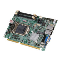
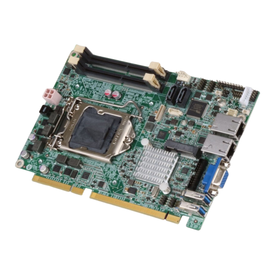
IEI Technology HPCIE-C236 User Manual (137 pages)
Half-size PICMG 1.3 CPU card supports LGA 1151 Intel Xeon E3, Core i3/Pentium /Celeron CPU with Intel C236, ECC & non-ECC DDR4 SO-DIMM, VGA, iDP, Intel GbE, USB 3.0, mSATA, SATA, PCIe Mini, Intel AMT and RoHS
Brand:
IEI Technology
| Category:
Motherboard
| Size: 8.71 MB
Table of Contents
User Manual
1
Table of Contents
5
1 Introduction
14
Figure 1-1: HPCIE-C236
15
Figure 1-2: Connectors
17
Figure 1-3: HPCIE-C236 Dimensions (MM)
18
Data Flow
19
Figure 1-4: Data Flow Diagram
19
Technical Specifications
20
Dimensions
18
Introduction
15
Features
16
Connectors
17
Table 1-1: HPCIE-C236 Specifications
22
2 Packing List
23
Anti-Static Precautions
24
Unpacking Precautions
24
Packing List
25
Table 2-1: Packing List
25
Optional Items
26
Table 2-2: Optional Items
27
3 Connectors
28
Figure 3-1: Peripheral Interface Connectors
29
Table 3-1: Peripheral Interface Connectors
30
Table 3-2: External Peripheral Connectors
31
Audio Kit Connector
32
External Interface Panel Connectors
31
Internal Peripheral Connectors
31
ATX Power Connector
31
Peripheral Interface Connectors
29
HPCIE-C236 Layout
29
Peripheral Interface Connectors
30
Figure 3-2: +12V ATX Power Connector Pinout Location
31
Figure 3-3: Audio Connector Location
32
Table 3-3: +12V ATX Power Connector Pinouts
32
Table 3-4: Audio Connector Pinouts
32
Figure 3-4: Battery Connector Location
33
Table 3-5: Battery Connector Pinouts
33
Figure 3-5: Buzzer Connector Location
34
Table 3-6: Buzzer Connector Pinouts
34
CRT FW Update Connector
35
Figure 3-6: Chassis Intrusion Connector Location
35
Figure 3-7: CRT FW Update Connector Location
35
Table 3-7: Chassis Intrusion Connector Pinouts
35
DDR4 SO-DIMM Slots
36
Figure 3-8: DDR4 SO-DIMM Slot Locations
36
Table 3-8: CRT FW Update Connector Pinouts
36
Digital I/O Connector
37
Figure 3-9: Digital I/O Connector Location
37
Table 3-9: Digital I/O Connector Pinouts
37
EC Debug Connector
38
Table 3-10: EC Debug Connector Pinouts
38
Fan Connector (CPU)
39
Buzzer Connector
34
Chassis Intrusion Connector
34
Battery Connector
33
Figure 3-10: EC Debug Connector Location
38
Figure 3-11: CPU Fan Connector Location
39
Table 3-11: CPU Fan Connector Pinouts
39
Figure 3-16: LAN LED Connector Locations
44
Figure 3-17: Pcie Mini Slot Location
45
Pcie Mini Slot
45
LAN LED Connectors
44
Table 3-16: LAN1 LED Connector (LED_LAN1) Pinouts
44
Table 3-17: LAN2 LED Connector (LED_LAN2) Pinouts
44
Figure 3-18: Power Button Location
46
Power Button
46
Table 3-18: Pcie Mini Slot Pinouts
46
Figure 3-19: RS-232/422/485 Serial Port Connector Locations
47
RS-232/422/485 Serial Port Connectors
47
Table 3-19: RS-232/422/485 Serial Port Connector Pinouts
47
Figure 3-20: SATA 6Gb/S Drive Connector Locations
48
SATA 6Gb/S Drive Connector
48
Table 3-20: DB-9 RS-232/422/485 Pinouts
48
Table 3-21: SATA 6Gb/S Drive Connector Pinouts
48
Figure 3-21: Smbus Connector Location
49
Smbus Connector
49
Table 3-22: Smbus Connector Pinouts
49
Figure 3-22: SPI Flash Connector Location
50
SPI Flash Connector
50
Table 3-23: SPI Flash Connector Pinouts
50
Figure 3-23: USB 2.0 Connector Locations
51
Table 3-24: USB 2.0 Connector Pinouts
51
USB 2.0 Connectors
51
Ethernet Connectors
52
External Peripheral Interface Connector Panel
52
Table 3-25: LAN Pinouts
52
USB 3.0 Connectors
53
VGA Connector
53
Figure 3-12: Front Panel Connector Location
40
Front Panel Connector
40
Table 3-12: Front Panel Connector Pinouts
40
Figure 3-13: I 2 C Connector Location
41
I 2 C Connector
41
Table 3-13: I 2 C Connector Pinouts
41
Figure 3-14: Internal Displayport Connector Location
42
Internal Displayport Connector
42
Table 3-14: Internal Displayport Connector Pinouts
42
Figure 3-15: Keyboard and Mouse Connector Location
43
Keyboard and Mouse Connector
43
Table 3-15: Keyboard and Mouse Connector Pinouts
43
Figure 3-24: External Peripheral Interface Connector
52
Figure 3-25: Ethernet Connector
52
Table 3-26: USB 3.0 Port Pinouts
53
Table 3-27: VGA Connector Pinouts
54
Figure 3-26: VGA Connector
54
4 Installation
55
Anti-Static Precautions
56
Installation Considerations
56
Figure 4-1: Disengage the CPU Socket Load Lever
58
Socket Lga1151 Cpu Installation
58
Figure 4-2: Remove Protective Cover
59
Figure 4-3: Insert the Socket LGA1151 CPU
60
Figure 4-4: Close the Socket LGA1151
60
Figure 4-5: Cooling Kit Support Bracket
62
Full-Size Pcie Mini Card Installation
63
So-DIMM Installation
63
Figure 4-6: SO-DIMM Installation
63
Figure 4-8: Inserting the Full-Size Pcie Mini Card into the Slot at an Angle
64
Figure 4-7: Removing the Retention Screw
64
Half-Size Pcie Mini Card Installation
65
Socket Lga1151 Cooling Kit Installation
61
Figure 4-9: Securing the Full-Size Pcie Mini Card
65
Figure 4-14: AT/ATX Power Mode Switch Location
68
Figure 4-15: Clear CMOS Button Location
68
Table 4-1: AT/ATX Power Mode Switch Settings
68
Figure 4-17: Flash Descriptor Security Override Jumper Location
70
Flash Descriptor Security Override Jumper
70
Pcie X16 Channel Mode Setup
70
Table 4-3: Pcie X16 Channel Mode Setup
70
Table 4-4: Flash Descriptor Security Override Jumper Settings
70
Table 4-5: BIOS Options and Configured USB Ports
71
Table 4-6: USB Power Source Setup
71
USB Power Selection
71
Figure 4-18: SATA Drive Cable Connection
72
Internal Peripheral Device Connections
72
SATA Drive Connection
72
Adding Usb 3.0 Drivers to a Windows 7 Installation Image
73
Figure 4-19: SATA Power Drive Connection
73
Figure 4-20: Windows 7 USB 3.0 Creator Utility
74
Figure 4-21: Update Process Is Complete
75
Intel ® Amt Setup Procedure
75
Figure 4-16: BIOS Switch Location
69
Pcie X4 Channel Mode Setup
69
Table 4-2: BIOS Switch Settings
69
Figure 4-10: Removing the Standoff
66
Figure 4-11: Installing the Standoff
66
Figure 4-12: Inserting the Half-Size Pcie Mini Card into the Slot at an Angle
67
Figure 4-13: Securing the Half-Size Pcie Mini Card
67
System Configuration
68
AT/ATX Power Mode Setting
68
Clear CMOS Button
68
5 Bios
77
Introduction
78
Starting Setup
78
Using Setup
78
Getting Help
79
Unable to Reboot after Configuration Changes
79
BIOS Menu Bar
79
Main
79
Table 5-1: BIOS Navigation Keys
79
BIOS Menu 1: Main
80
Advanced
81
ACPI Settings
82
AMT Configuration
83
Super IO Configuration
84
Serial Port N Configuration
85
Iwdd H/W Monitor
88
Smart Fan Mode Configuration
89
RTC Wake Settings
90
Serial Port Console Redirection
91
Legacy Console Redirection Settings
93
CPU Configuration
94
SATA Configuration
96
Nvme Configuration
97
USB Configuration
98
Iei Feature
99
Chipset
100
System Agent (SA) Configuration
101
Graphics Configuration
102
PEG Port Configuration
104
Memory Configuration
105
PCH-IO Configuration
106
Table 5-2: BIOS Options and Configured USB Ports
107
PCI Express Configuration
108
BIOS Menu 25: PCI Express Port 1/2/3/4
109
HD Audio Configuration
110
Security
111
Boot
112
Save & Exit
114
BIOS Menu 29: Save & Exit
114
6 Software Drivers
115
Available Software Drivers
116
Software Installation
116
Figure 6-1: Available Drivers
117
A Regulatory Compliance
118
B Product Disposal
120
CBIOS Options
122
D Terminology
125
E Digital I/O Interface
129
Introduction
130
Assembly Language Sample 1
131
Assembly Language Sample
131
F Watchdog Timer
132
G Hazardous Materials Disclosure
135
Advertisement
Advertisement
Related Products
IEI Technology HPCIE-Q170
IEI Technology HPCIE-C236-R10
IEI Technology HYPER-BT
IEI Technology HYPER-KBN
IEI Technology HYPER-BW
IEI Technology HYPER-RK39
IEI Technology HPCIE-Q470
IEI HDC-304E
IEI Technology HYPER-BT-N28071
IEI Technology A200C-800Z-R10
IEI Technology Categories
Motherboard
Touch Panel
Computer Hardware
Single board computers
Desktop
More IEI Technology Manuals
Login
Sign In
OR
Sign in with Facebook
Sign in with Google
Upload manual
Upload from disk
Upload from URL