Sign In
Upload
Manuals
Brands
IEI Technology Manuals
Touch Panel
AFL4-W10-EHL
IEI Technology AFL4-W10-EHL Manuals
Manuals and User Guides for IEI Technology AFL4-W10-EHL. We have
1
IEI Technology AFL4-W10-EHL manual available for free PDF download: User Manual
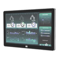
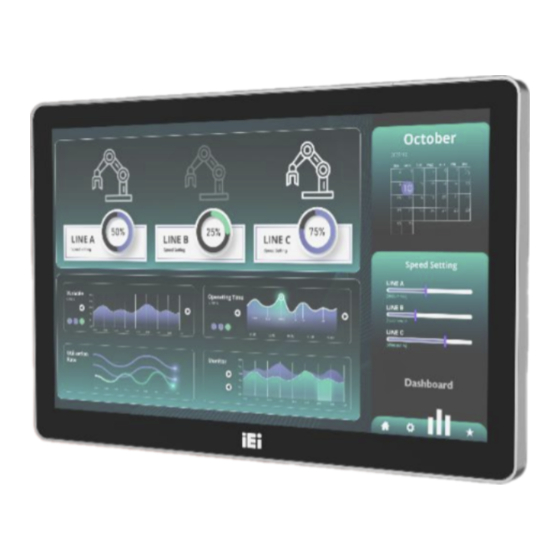
IEI Technology AFL4-W10-EHL User Manual (135 pages)
Panel PC equips Intel Celeron J6412 on-board processor, 8GB LPDDR4X on-board, IEEE 802.11 a/b/g/n/ax, Bluetooth V5.2, one M.2 2242 M key Slot, one M.2 2242 M key Slot
Brand:
IEI Technology
| Category:
Touch Panel
| Size: 6 MB
Table of Contents
Table of Contents
8
Introduction
16
Overview
17
Model Variations
17
Figure 1-1: AFL4-W10/W12/12/W13 Panel PC
17
Table 1-1: Model Variation
17
Features
18
Front Panel
18
Rear Panel
18
Figure 1-2: Front View
18
Bottom Panel
19
Figure 1-3: Rear View
19
Figure 1-4: Front Bottom Panel
19
Figure 1-5: Left Bottom Panel
19
System Specifications
20
Figure 1-6: Right Bottom Panel
20
Wlan/Bluetooth Frequency Range and Power
22
Table 1-2: System Specifications
22
Table 1-3: Wlan/Bluetooth Frequency Range and Power
22
Dimensions
23
AFL4-W10-EHL Dimensions
23
Figure 1-7: AFL4-W10-EHL Dimensions (MM)
23
AFL4-W12-EHL Dimensions
24
Figure 1-8: AFL4-W12-EHL Dimensions (MM)
24
AFL4-12-EHL Dimensions
25
Figure 1-9: AFL4-12-EHL Dimensions (MM)
25
AFL4-W13-EHL Dimensions
26
Figure 1-10: AFL4-W13-EHL Dimensions (MM)
26
Unpacking
27
Unpacking
28
Packing List
29
Table 2-1: Packing List
29
Optional Items
30
Table 2-2: Optional Items
30
Installation
31
Anti-Static Precautions
32
Installation Precautions
32
Installation and Configuration Steps
33
Removing the
33
Module Installation
34
Figure 3-1: Back Cover Retention Screws
34
Figure 3-2: Remove the Back Cover
34
Clear Cmos
35
Figure 3-3: M.2 Module Slot Location
35
Figure 3-4: M.2 Module Installation
35
At/Atx Mode Selection
36
AT Power Mode
36
Figure 3-5: Clear CMOS Button Location
36
Figure 3-6: AT/ATX Switch Location
36
ATX Power Mode
37
Mounting the System
37
Wall Mounting
37
Figure 3-7: Wall-Mounting Bracket
38
Figure 3-8: Chassis Support Screws
39
Arm Mounting
40
Figure 3-9: Secure the Panel PC
40
Figure 3-10: Arm Mounting Retention Screw Holes
41
Figure 3-11: Arm Mounting
41
Stand Mounting
42
V-Stand Mounting
42
Figure 3-12: Stand Mounting (Stand-CXX)
42
Figure 3-13: Drill Pilot Holes for V-Stand
43
Figure 3-14: Secure V-Stand to System
43
Powering on the System
44
Figure 3-15: Secure V-Stand to Mounting Area
44
Reset the System
45
Software Installation
45
Figure 3-16: Power Button
45
Figure 3-17: Reset Button Location
45
Driver Download
46
Figure 3-18: IEI Resource Download Center
46
Adjust Brightlight
47
Figure 3-19: Keypad AP
47
System Maintenance
48
System Maintenance Introduction
49
Anti-Static Precautions
49
Turn off the Power
50
Wlan Card Replacement
50
Figure 4-1: WLAN Module Location
50
Figure 4-2: Releasing the WLAN Module
51
Figure 4-3: Removing the WLAN Module
51
Reinstalling the Cover
52
Bios
53
Introduction
54
Starting Setup
54
Figure 5-1: BIOS Starting Menu
54
Using Setup
55
Table 5-1: BIOS Navigation Keys
55
Table 5-2: BIOS On-Screen Navigation Keys
56
Getting Help
57
Unable to Reboot after Configuration Changes
57
BIOS Menu Bar
57
Main
58
Advanced
62
CPU Configuration
63
Trusted Computing
67
F81966 Super IO Configuration
68
EC KB9068 H/W Monitor
75
Serial Port Console Redirection
79
Nvme Configuration
83
Chipset
84
System Agent (SA) Configuration
85
PCH-IO Configuration
90
Security
97
Boot
99
Boot Configuration
99
Boot Option Priorities
100
Save & Exit
101
Connectors
103
Peripheral Interface Connectors
104
Figure 5-1: Main Board Layout Diagram (Front Side)
104
Figure 5-2: Main Board Layout Diagram (Solder Side)
104
Internal Peripheral Connectors
105
Touch Panel Connector (TOUCH_USB1)
105
Table 5-1: Peripheral Interface Connectors
105
Table 5-2: Touch Panel Connector (TOUCH_USB1) Pinouts
105
Flash SPI ROM Connector (JBIOS1)
106
EC Debug Port Connector (EC_DEBUG1)
106
Speaker Connector (SPK_L1)
106
RFID Connector (RFID_USB1)
106
Table 5-3: Flash SPI ROM Connector (JBIOS1) Pinouts
106
Table 5-4: EC Debug Port Connector (EC_DEBUG1) Pinouts
106
Table 5-5: Speaker Connector (SPK_L1) Pinouts
106
Table 5-6: RFID Connector (RFID_USB1) Pinouts
106
Digital MIC Connector (DMIC1)
107
I²C Connector (I2C1)
107
Smbus Connector (SMB1)
107
Battery Connector (BAT1)
107
A-Key Slot (M2_AE1)
107
Table 5-7: Digital MIC Connector (DMIC1) Pinouts
107
Table 5-8: I² C Connector (I2C1) Pinouts
107
Table 5-9: Smbus Connector (SMB1) Pinouts
107
Table 5-10: Battery Connector (BAT1) Pinouts
107
M-Key Slot (M2_M1)
109
Table 5-11: M.2 A-Key Slot (M2_AE1) Pinouts
109
M-Key Slot (M2_M2)
110
Table 5-12: M.2 M-Key Slot (M2_M1) Pinouts
110
Edp Connector (EDP1)
111
Table 5-13: M.2 M-Key Slot (M2_M2) Pinouts
111
LVDS Connector (LCD1)
112
LVDS Backlight Power (INV1)
112
Table 5-14: Edp Connector (EDP1) Pinouts
112
Table 5-15: LVDS Connector (LCD1) Pinouts
112
CPU Fan Connector (CPU_FAN1)
113
Jumper Less Setting
113
PWM Power Selection (J_PWM1)
113
Backlight Enable Selection (J_BL_EN)
113
Table 5-16: LVDS Backlight Power (INV1) Pinouts
113
Table 5-17: CPU Fan Connector (CPU_FAN1) Pinouts
113
Table 5-18: Jumper Less Setting
113
Table 5-19: PWM Power Selection (J_PWM1)
113
Table 5-20: Backlight Enable Selection (J_BL_EN)
113
Backlight VCC Selection (J_BL_VCC)
114
LVDS Power Selection (J_VLVDS1)
114
Flash Descriptor Security Override
114
External Interface Panel Connectors
114
Table 5-21: Backlight VCC Selection (J_BL_VCC)
114
Table 5-22: LVDS Power Selection (J_VLVDS1)
114
Table 5-23: Flash Descriptor Security Override
114
Table 5-24: External Interface Panel Connectors
114
RS-232/422/485 Serial Ports (COM1/2/3/4)
115
RJ45 LAN Connector (J_LAN1/2)
115
HDMI Connector (HDMI1)
115
Advertisement
Advertisement
Related Products
IEI Technology AFL4-W101-ADLP
IEI Technology AFL4-W101-ADLP-i3/8G
IEI Technology AFL4-W101-ADLP-i5/8G
IEI Technology AFL4-W101-ADLP-i7/8G
IEI Technology AFL4-W101-ADLP-C/8G-R10
IEI Technology AFL4-W101-ADLP-i7/8G-R10
IEI Technology AFL4-W133-ADLP-i3/8G-R10
IEI Technology AFL4-W133-ADLP-i7/8G-R10
IEI Technology AFL4-W121-ADLP-C/8G-R10
IEI Technology AFL4-W133-ADLP-i5/8G
IEI Technology Categories
Motherboard
Touch Panel
Computer Hardware
Single board computers
Desktop
More IEI Technology Manuals
Login
Sign In
OR
Sign in with Facebook
Sign in with Google
Upload manual
Upload from disk
Upload from URL