Sign In
Upload
Manuals
Brands
IEI Technology Manuals
Touch Panel
AFL4-W07-RK3566
IEI Technology AFL4-W07-RK3566 Manuals
Manuals and User Guides for IEI Technology AFL4-W07-RK3566. We have
1
IEI Technology AFL4-W07-RK3566 manual available for free PDF download: User Manual
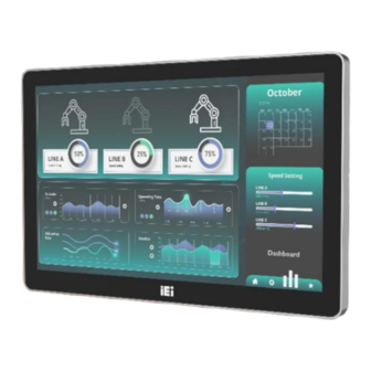
IEI Technology AFL4-W07-RK3566 User Manual (69 pages)
7" Fanless Panel PC with RK3566, 2/4GB LPDDR4/4X, 16/32GB eMMC, 1xUSB2.0, 1xUSB3.0, 2xRS-232/422/485, HDMI, 1xRJ45, 12V DC IN, PCAP touch, Debian10/Android12, RoHS
Brand:
IEI Technology
| Category:
Touch Panel
| Size: 8 MB
Table of Contents
Safety Instructions
3
Manual Conventions
6
Table of Contents
7
Introduction
13
Overview
14
Model Variations
14
Figure 1-1: AFL4-W07-RK3566 Panel PC
14
Table 1-1: Model Variation
14
Features
15
Front Panel
15
Rear Panel
15
Figure 1-2: Front View
15
Figure 1-3: Rear View
15
Bottom Panel
16
Figure 1-4: Front Bottom Panel
16
Figure 1-5: Left Bottom Panel
16
Figure 1-6: Right Bottom Panel
16
System Specifications
17
Table 1-2: System Specifications
18
Dimensions
19
Figure 1-7: AFL4-W07-RK3566 Dimensions (MM)
19
Unpacking
20
Npacking
21
Packing List
22
Table 2-1: Packing List
22
Optional Items
23
Table 2-2: Optional Items
23
Installation
24
Anti-Static Precautions
25
Installation Precautions
25
Removing the
26
Removing the Back Cover
26
Figure 3-1: Back Cover Retention Screws
26
Patch Antenna Installation
27
Figure 3-2: Remove the Back Cover
27
Figure 3-3: Take out the Patch Antenna
27
5G Module Installation
28
Figure 3-4: Fix the Patch Antenna
28
Figure 3-5: Route Antenna to the Module
28
Figure 3-6: M.2 Module Slot Location
29
Figure 3-7: M.2 Module Installation
29
Iei Board to Board Wifi Module Installation
30
Figure 3-8: Buckle the Antenna Connector
30
Figure 3-9: WIFI Module Slot Location
30
Otg Mode Selection
31
Figure 3-10: WIFI Module Installation
31
Figure 3-11: Lock Screws and Buckle the Antenna
31
Os Image Program Switch
32
Figure 3-12: USB OTG Switch Location
32
Figure 3-13: IMAGE-SW1 Location
32
Figure 3-14: Software Screen (1)
33
Figure 3-15: Software Screen (2)
33
Install the
34
Figure 3-16: Software Screen (3)
34
Figure 3-17: Thermal Pad
34
Mounting the System
35
Wall Mounting
35
Figure 3-18: Install the Back Cover
35
Figure 3-19: Wall-Mounting Bracket
36
Figure 3-20: Chassis Support Screws
37
Arm Mounting
38
Figure 3-21: Secure the Panel PC
38
Stand Mounting
39
Figure 3-22: Arm Mounting Retention Screw Holes
39
Figure 3-23: Arm Mounting
39
V-Stand Mounting
40
Figure 3-24: Stand Mounting (Stand-CXX)
40
Figure 3-25: Drill Pilot Holes for V-Stand
41
Figure 3-26: Secure V-Stand to System
41
Powering on the System
42
Figure 3-27: Secure V-Stand to Mounting Area
42
Reset the System
43
Figure 3-28: Power Button
43
Figure 3-29: Reset Button Location
43
Connectors
44
Peripheral Interface Connectors
45
Internal Peripheral Connectors
45
Figure 4-1: Main Board Layout Diagram (Front Side)
45
Figure 4-2: Main Board Layout Diagram (Solder Side)
45
Touch Panel Connector (CN3)
46
Debug Port Connector (DEBUG_CN1)
46
Speaker Connector (SPK1)
46
Table 4-1: Peripheral Interface Connectors
46
Table 4-2: Touch Panel Connector (CN3) Pinouts
46
Table 4-3: Debug Port Connector (DEBUG_CN1) Pinouts
46
Table 4-4: D Speaker Connector (SPK1) Pinouts
46
Board to Board Connector (CN2)
47
OS Image Program Switch (IMAGE_SW1)
47
Table 4-5: Board to Board Connector (CN2) Pinouts
47
Table 4-6: 5.2.5 os Image Program Switch (IMAGE_SW1) Pinouts
47
Battery Connector (BAT1)
48
LVDS Connector (LVDS2)
48
B-Key Slot (NGFF1)
48
Table 4-7: 5.2.7 Battery Connector (BAT1) Pinouts
48
Table 4-8: LVDS Connector (LVDS2) Pinouts
48
External Interface Panel Connectors
50
Serial Ports (COM1/2)
50
Table 4-9: 5.2.8 M.2 B-Key Slot (NGFF) Pinouts
50
Table 4-10: External Interface Panel Connectors
50
Audio Connector (AUDIO_JACK1)
51
Reset Button (RST1)
51
SD Card (SD1)
51
Table 4-11: COM1/2 Connector Pinouts
51
Table 4-12: Audio Connector (AUDIO_JACK1) Pinouts
51
Table 4-13: Reset Button (RST1) Pinouts
51
Table 4-14: SD Card (SD1) Pinouts
51
SIM Card (SIM1)
52
USB OTG Mode Switch (OTG_ID1)
52
RJ45 LAN Connector (LAN1)
52
HDMI Connector (HDMI1)
52
Table 4-15: SIM Card (SIM1) Pinouts
52
Table 4-16: USB OTG Mode Switch (OTG_ID1) Pinouts
52
Table 4-17: LAN Connector (J_LAN1/2) Pinouts
52
USB 2.0 Connectors (USB_CON1)
53
USB 3.0 Connectors (CON1)
53
Power Button (PWR_SW1)
53
Table 4-18: HDMI1 Connector (HDMI1) Pinouts
53
Table 4-19: USB 2.0 Connectors (USB_CON1) Pinouts
53
Table 4-20: USB 3.2 Gen 2 Connectors (CON1) Pinouts
53
Table 4-21: Power Button (PWR_SW1) Pinouts
53
DC Jack (PWR1)
54
Table 4-22: DC Jack Connector
54
Regulatory Compliance
55
Safety Precautions
61
Safety Precautions
62
General Safety Precautions
62
Anti-Static Precautions
63
Product Disposal
64
Maintenance and Cleaning Precautions
65
Maintenance and Cleaning
65
Cleaning Tools
66
Hazardous Materials Disclosure
67
Rohs II Directive (2015/863/EU)
68
China Rohs
69
Advertisement
Advertisement
Related Products
IEI Technology AFL4-W07-EHL
IEI Technology AFL4-W101-ADLP-i3/8G
IEI Technology AFL4-W101-ADLP-i5/8G
IEI Technology AFL4-W121-ADLP-i3/8G
IEI Technology AFL4-W121-ADLP-i5/8G
IEI Technology AFL4-W121-ADLP-i7/8G
IEI Technology AFL4-W133-ADLP-i7/8G
IEI Technology AFL4-W121-ADLP-i5/8G-R10
IEI Technology AFL4-W101-ADLP-i7/8G-R10
IEI Technology AFL4-W133-ADLP-i3/8G-R10
IEI Technology Categories
Motherboard
Touch Panel
Computer Hardware
Single board computers
Desktop
More IEI Technology Manuals
Login
Sign In
OR
Sign in with Facebook
Sign in with Google
Upload manual
Upload from disk
Upload from URL