Sign In
Upload
Manuals
Brands
IEI Technology Manuals
Touch Panel
AFL2-12A-D525/R-MF/1G-R10
IEI Technology AFL2-12A-D525/R-MF/1G-R10 Manuals
Manuals and User Guides for IEI Technology AFL2-12A-D525/R-MF/1G-R10. We have
1
IEI Technology AFL2-12A-D525/R-MF/1G-R10 manual available for free PDF download: User Manual
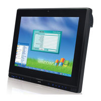
IEI Technology AFL2-12A-D525/R-MF/1G-R10 User Manual (180 pages)
Fanless Flat Bezel Panel PC with 1.8 GHz Intel Atom Processor TFT LCD, WI-Fi, Touch Screen, RFOD reader, Dual GbE LAN RS/232/422/485, Camera, RoHS
Brand:
IEI Technology
| Category:
Touch Panel
| Size: 5 MB
Table of Contents
Table of Contents
5
1 Introduction
15
Afl2-12A-D525 Flat Bezel Panel Pc Overview
16
Model Variations
16
Figure 1-1: AFL2-12A-D525 Flat Bezel Panel PC
16
Applications
17
Features
17
Table 1-1: AFL2-12A-D525 Model Variations
17
External Overview
18
Front Panel
18
Figure 1-2: AFL2-12A-D525 Front View
18
Figure 1-3: LED Indicators
19
LED Indicators
19
Table 1-2: LED Indicators
20
Figure 1-4: Function Keys
20
Table 1-3: Function Key Descriptions
21
I/O Interface Panel
22
Figure 1-5: AFL2-12A-D525 Rear View
21
Rear Panel
21
Figure 1-6: AFL2-12A-D525 I/O Interface Panel
23
Figure 1-7: Top Panel View
23
Top Panel and Side Panels
23
Figure 1-8: Side Panel Views
24
Internal Overview
24
System Specifications
24
Table 1-4: System Specifications
26
2 Detailed Specifications
27
Dimensions
28
Figure 2-1: AFL2-12A-D525 Dimensions (MM)
28
Intel® Atom™ Processor
29
Motherboard Components
29
Figure 2-2: AFL2-12A-D525 Dimensions (MM) Cont
29
Memory Support
30
Installed Memory
30
Storage Capacity
30
External Peripheral Interface Connectors
30
Serial Port Connectors
30
Figure 2-3: COM Ports
30
External USB Connectors
31
LAN Connectivity
31
Touchscreen Lcd
31
Monitor
31
Figure 2-4: RJ-45 Ethernet Connectors
31
Figure 2-5: External USB Ports
31
Audio
32
Audio Codec Controller
32
Figure 2-6: LCD Screen
32
Figure 2-7: Audio Jack
32
Touch-Screen Module
32
Stereo Speakers
33
System Power
33
AT Power Mode
33
ATX Power Mode (Default)
33
Power Mode
33
Power Adapter
34
3 Unpacking
35
Unpacking
36
Packing List
36
4 Installation
40
Anti-Static Precautions
41
Installation Precautions
41
Installation and Configuration Steps
42
Hdd Installation
42
Figure 4-1: HDD Cover Retention Screws
43
Figure4-2: HDD Bracket Screw
43
Figure4-3: Removing the HDD Bracket
44
Figure 4-4: Inserting the HDD
44
Cf Card Installation
45
Figure4-5: Securing the HDD
45
Figure 4-6: HDD Cover Retention Screws
46
Figure4-7: CF Card Slot Location
46
At/Atx Mode Selection
47
AT Power Mode
47
Figure 4-8: Inserting the CF Card
47
Figure 4-9: AT/ATX Switch Location
47
ATX Power Mode
48
Powering off the System
48
Powering on the System
48
Mounting the System
49
Wall Mounting
49
Figure 4-10: Wall-Mounting Bracket
50
Figure 4-11: Chassis Support Screws
51
Figure 4-12: Secure the Panel PC
52
Figure 4-13: Mounting Screw Location
52
Stand Mounting
52
Arm Mounting
53
Cabinet and Rack Installation
54
Figure 4-14: Arm Mounting Retention Screw Holes
54
Figure 4-15: the Rack/Cabinet Bracket
55
Figure 4-16: Secure the Rack/Cabinet Bracket
55
Bottom Panel Connectors
56
LAN Connection
56
Figure 4-17: Install into a Rack/Cabinet
56
Serial Device Connection
57
Serial Port Connection
57
Figure 4-18: LAN Connection
57
Figure 4-19: DB-9 Connector
58
Table 4-1: DB-9 Connector Pinouts
58
Figure 4-20: DB-9 Serial Port Connector
59
Serial Port Connection
59
Figure 4-21: Ethernet Connector
60
Table 4-2: Ethernet Connector Pinouts
60
Figure 4-22: RJ-45 Serial Port Connector
60
Figure 4-23: RS-422/485 Serial Port
61
Table 4-3: RS-422/485 Serial Port Pinouts
61
Figure 4-24: RS-422/485 Cable
61
RS-422/485 Serial Port
61
Table 4-4: DB-9 Connector Pinouts
62
USB Device Connection
62
Figure 4-25: DB-9 Connector
62
Figure 4-26: USB Device Connection
63
5 System Maintenance
64
System Maintenance Introduction
65
Anti-Static Precautions
65
Turn off the Power
66
Opening the System
66
Removing the
66
Removing the Internal Aluminum Cover
67
Figure 5-1: Back Cover Retention Screws
67
Replacing Components
68
Memory Module Replacement
68
Figure5-2: Internal Cover Retention Screws
68
Figure 5-3: DDR SO-DIMM Module Installation
69
WLAN Card Replacement
69
Figure5-4: Removing the Antennas
70
Figure5-5: Releasing the WLAN Card
70
Figure5-6: Removing the WLAN Card
71
Figure5-7: Attaching the Antennas
72
Reinstalling the Covers
73
6 Ami Bios Setup
74
Introduction
75
Starting Setup
75
Using Setup
75
BIOS Menu Bar
76
Getting Help
76
Unable to Reboot after Configuration Changes
76
Table 6-1: BIOS Navigation Keys
76
Main
77
System Date [XX/XX/XX]
77
System Overview
77
Advanced
78
System Time [XX:XX:XX]
78
ACPI Settings
79
CPU Configuration
80
ACPI Sleep State [S1 (CPU Stop Clock)]
80
Power Saving Function [Disabled]
80
IDE Configuration
82
ATA/IDE Configuration [Enhanced]
82
Configure SATA as [IDE]
82
USB Configuration
83
Legacy USB Support [Enabled]
83
USB Devices
83
Generic STORAGE DEVICE 9454 [Auto]
84
Serial Port N Configuration
85
Super IO Configuration
85
Change Settings [Auto]
86
Serial Port [Enabled]
86
Change Settings [Auto]
87
H/W Monitor
88
Serial Port Console Redirection
89
Select Serial Mode [Auto]
87
Serial Port [Enabled]
87
PC Health Status
89
Console Redirection [Disabled]
90
Auto Recovery Function [Disabled]
91
Iei Feature
91
Chipset
92
Host Bridge Configuration
93
South Bridge Configuration
94
HD Audio Controller [Enabled]
94
Restore AC Power Loss [Power Off]
94
DMIC Function [Enabled]
95
Intel IGD SWSCI Opregion
96
Set Spread Spectrum Function [Disabled]
95
USB 2.0(EHCI) Support [Enabled]
95
USB Function [Enabled]
95
WIFI Function [Enabled]
95
Autodimming Function [Enabled]
96
BT Function [Enabled]
96
DVMT Mode Select [DVMT Mode]
97
DVMT/FIXED Memory [Maximum]
97
IGD - Boot Type [CRT + LFP]
97
LCD Panel Type [1024X768 18Bit]
97
Boot
98
Bootup Numlock State [On]
98
Boot Option #1 [Generic STORAGE de
99
Hard Drive BBS Priorities
99
Launch PXE Oprom [Disabled]
99
Quiet Boot [Enabled]
99
Administrator Password
100
Security
100
Set User Password
100
User Password
100
HDD Password Configuration
101
Set Master Password
101
Discard Changes and Reset
102
Restore Defaults
102
Save & Exit
102
Save Changes and Reset
102
Restore User Defaults
103
Save as User Defaults
103
7 Software Drivers
104
Available Software Drivers
105
Starting the Driver Program
105
Chipset Driver Installation
105
Figure 7-1: Chipset Driver Screen
106
Figure 7-2: Chipset Driver Welcome Screen
106
Figure 7-3: Chipset Driver License Agreement
107
Figure 7-4: Chipset Driver Read Me File
108
Figure 7-5: Chipset Driver Setup Operations
108
Graphics Driver Installation
109
Figure 7-6: Chipset Driver Installation Finish Screen
109
Figure 7-7: Graphics Driver Read Me File
110
Figure 7-8: Graphics Driver Setup Files Extracted
110
Figure 7-9: Graphics Driver Welcome Screen
111
Figure 7-10: Graphics Driver License Agreement
111
Figure 7-11: Graphics Driver Read Me File
112
Figure 7-12: Graphics Driver Setup Operations
112
Audio Driver Installation
113
Figure 7-13: Graphics Driver Installation Finish Screen
113
Figure 7-14: Audio Driver Welcome Screen
114
Figure 7-15: Audio Driver Installation
114
Touch Screen Driver
115
Figure 7-16: AC'97 Driver Installation Complete
115
Figure 7-17: Touch Screen Driver Welcome Screen
116
Figure 7-18: Touch Screen Driver License Agreement
116
Figure 7-19: Touch Screen Driver Choose Install Location
117
Figure 7-20: Touch Screen Driver Installation Screen
118
Figure 7-21: Touch Screen Driver Update Complete
118
Calibrating the Touch Screen
119
Figure 7-22: Penmount Monitor Icon
119
Figure 7-23: Penmount Monitor Popup Menu
119
Figure 7-24: Configuration Screen
120
Figure 7-25: Calibration Initiation Screen
120
Amcap Driver Installation
121
Figure 7-26: Calibration Screen
121
Figure 7-27: Amcap Driver Welcome Screen
122
Figure 7-28: Amcap Driver Choose Install Location
122
Figure 7-29: Amcap Driver Installation Complete
123
A Safety Precautions
124
Safety Precautions
125
General Safety Precautions
125
CPU Temperature Warning
126
Product Disposal
126
Anti-Static Precautions
127
Product Disposal
128
Maintenance and Cleaning Precautions
128
Maintenance and Cleaning
128
Cleaning Tools
129
B Bios Configuration Options
130
B.1 BIOS Configuration Options
131
Bios Configuration Options
131
C One Key Recovery
133
One Key Recovery Introduction
134
Figure C-1: IEI One Key Recovery Tool Menu
134
System Requirement
135
Supported Operating System
136
Setup Procedure for Windows
137
Create Partitions
138
Hardware and BIOS Setup
138
Figure C-2: Launching the Recovery Tool
139
Figure C-3: Recovery Tool Setup Menu
139
Figure C-4: Command Prompt
140
Figure C-5: Partition Creation Commands
141
Install Operating System, Drivers and Applications
142
Building the Recovery Partition
143
Figure C-6: Launching the Recovery Tool
143
Figure C-7: Manual Recovery Environment for Windows
143
Figure C-8: Building the Recovery Partition
144
Figure C-9: Press any Key to Continue
144
Create Factory Default Image
145
Figure C-10: Press F3 to Boot into Recovery Mode
145
Figure C-11: Recovery Tool Menu
145
Figure C-12: about Symantec Ghost Window
146
Figure C-13: Symantec Ghost Path
146
Figure C-14: Select a Local Source Drive
147
Figure C-15: Select a Source Partition from Basic Drive
147
Figure C-16: File Name to Copy Image to
148
Figure C-17: Compress Image
148
Figure C-18: Image Creation Confirmation
149
Figure C-19: Image Creation Complete
149
Figure C-20: Image Creation Complete
149
Auto Recovery Setup Procedure
150
Figure C-21: Press any Key to Continue
150
Figure C-22: Auto Recovery Utility
151
Figure C-23: Launching the Recovery Tool
151
Figure C-24: Auto Recovery Environment for Windows
151
Figure C-25: Building the Auto Recovery Partition
152
Figure C-26: Factory Default Image Confirmation
152
Figure C-27: Image Creation Complete
153
Figure C-28: Press any Key to Continue
153
Setup Procedure for Linux
154
Figure C-29: Partitions for Linux
155
Figure C-30: Manual Recovery Environment for Linux
156
Figure C-31: Access Menu.lst in Linux (Text Mode)
157
Figure C-32: Recovery Tool Menu
157
C.5 R Ecovery T Ool F Unctions
158
Figure C-33: Recovery Tool Main Menu
158
Factory Restore
159
Figure C-34: Restore Factory Default
159
Backup System
160
Figure C-35: Recovery Complete Window
160
Figure C-36: Backup System
160
Restore Your Last Backup
161
Figure C-37: System Backup Complete Window
161
Figure C-38: Restore Backup
161
Manual
162
Figure C-39: Restore System Backup Complete Window
162
Figure C-40: Symantec Ghost Window
162
Recovery Tool Functions
158
Restore Systems from a Linux Server through Lan
163
Configure DHCP Server Settings
164
Configure TFTP Settings
165
Configure One Key Recovery Server Settings
166
Create Shared Directory
167
Start the DHCP, TFTP and HTTP
167
Setup a Client System for Auto Recovery
168
C.7 O Ther I Nformation
171
Using AHCI Mode or Ali M5283 / VIA VT6421A Controller
171
System Memory Requirement
173
Other Information
171
D Watchdog Timer
174
Example Program
176
E Hazardous Materials Disclosure
177
Hazardous Material Disclosure Table for IPB Products Certified as Rohs Compliant under 2002/95/EC Without Mercury
178
E.1 H Azardous M Aterial D Isclosure T Able for Ipb P Roducts C Ertified as R O Hs C Ompliant U Nder 2002/95/Ec W Ithout M Ercury
178
Advertisement
Advertisement
Related Products
IEI Technology AFL2-12A-D525/PC-EM/1G-R10
IEI Technology AFL2-12A-D525/PC-MF/1G-R10
IEI Technology AFL2-12A-D525/PC/1G-R10
IEI Technology AFL2-12A-D525/R-EM/1G-R10
IEI Technology AFL2-12A-D525/R/1G-R10
IEI Technology AFL2-12A-HM65/PC-EM-R11
IEI Technology AFL2-12A-HM65/PC-MF-R11
IEI Technology AFL2-12A-HM65/PC-R11
IEI Technology AFL2-12A-HM65/R-EM-R11
IEI Technology AFL2-12A-HM65/R-MF-R11
IEI Technology Categories
Motherboard
Touch Panel
Computer Hardware
Single board computers
Desktop
More IEI Technology Manuals
Login
Sign In
OR
Sign in with Facebook
Sign in with Google
Upload manual
Upload from disk
Upload from URL