Sign In
Upload
Manuals
Brands
IEI Technology Manuals
Touch Panel
AFL-517A-GM45
IEI Technology AFL-517A-GM45 Manuals
Manuals and User Guides for IEI Technology AFL-517A-GM45. We have
1
IEI Technology AFL-517A-GM45 manual available for free PDF download: User Manual
IEI Technology AFL-517A-GM45 User Manual (136 pages)
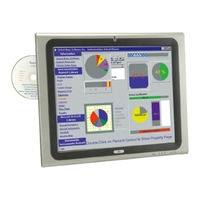
High Performance Panel PC with Intel Core2 Duo CPU Fan less, Touch Screen, 802.11 b/g/n Wireless LAN, Gigabit Ethernet, HDMI, DisplayPort, USB, Audio, RS-232/422/485, SATA, RoHS Compliant, IP 64 Protection
Brand:
IEI Technology
| Category:
Touch Panel
| Size: 10 MB
Table of Contents
Table of Contents
4
1 Introduction
12
Overview
13
Figure 1-1: AFL-517A-GM45 Flat Panel PC
13
Features
14
External Overview
14
Front Panel
14
Rear Panel
15
Figure 1-2: AFL-517A-GM45 Front View
15
Figure 1-3: AFL-517A-GM45 Rear View
16
I/O Interface Panel
16
Figure 1-4: AFL-517A-GM45 I/O Interface Connector Panel
17
Internal Overview
17
Model Variations
17
System Specifications
18
Table 1-1: AFL-517A-GM45 Specifications
18
Dimensions
20
Table 1-2: AFL-517A-GM45 Specifications
20
Figure 1-5: AFL-517A-GM45 Dimensions (MM)
20
2 Installation
21
Unpack the Panel Pc
22
Packing List
23
Removing the Rear Panel
26
Figure 2-1: Back Cover Retention Screws
26
Figure 2-2: Aluminum Cover Retention Screws
27
Cf Card Installation
28
Figure 2-3: HDD Bay Bracket Retention Screws and SATA Cable Locations
28
Hard Drive Installation
29
Figure 2-4: CF Card Slot Location
29
At/Atx Mode Selection
30
Figure 2-5: HDD Retention Screws
30
Figure 2-6: AT/ATX Switch Location
30
AT Power Mode
31
ATX Power Mode
31
Jumper Settings
32
Accessing the Jumpers
32
Table 2-1: Jumpers
32
Clear CMOS Jumper
33
Preconfigured Jumpers
33
Table 2-2: Preconfigured Jumpers
33
COM1, COM3 Port Pin 9 Select
34
Table 2-3: Clear CMOS Jumper Settings
34
COM3 RX Function Select Jumper
35
Figure 2-7: Clear CMOS Jumper
34
Table 2-4: COM1 Pin 9 Setting Jumper Settings
35
COM3 TX Function Select Jumper
36
Figure 2-8: COM1 and COM3 Pin 9 Setting Jumper Locations
35
Table 2-5: COM3 RX Function Select Jumper Settings
36
COM3 RS-232/422/485 Serial Port Select Jumper
37
Figure 2-9: COM3 RX Function Select Jumper Location
36
Table 2-6: COM3 TX Function Select Jumper Settings
37
Figure 2-10: COM3 TX Function Select Jumper Pinout Locations
37
Table 2-7: COM3 RS-232/422/485 Serial Port Select Jumper Settings
38
Figure 2-11: COM3 RS-232/422/485 Serial Port Select Jumper Location
39
Wall Surface Mounting
40
Figure 2-12: Wall-Mounting Bracket
40
Figure 2-13: Chassis Support Screws
41
Panel Mounting
42
Figure 2-14: Secure the Panel PC
42
Figure 2-15: AFL-517A-GM45 Cutout Dimensions (Units in MM)
43
Cabinet and Rack Installation
44
Figure 2-16: Tighten the Panel Mounting Clamp Screws
44
Figure 2-17: the Rack/Cabinet Bracket
45
Figure 2-18: Secure the Rack/Cabinet Bracket
45
Arm Mounting
46
Figure 2-19: Install into a Rack/Cabinet
46
Figure 2-20: AFL-412A-N270 Arm Mounting Retention Screw Holes
47
Mounting the System
39
Bottom Panel Connectors
48
LAN Connection
48
Figure 2-21: AFL-517A-GM45 I/O Interface Connector Panel
48
Figure 2-22: LAN Connection
49
COM3 RS-232, RS-422 and RS-485 Pinouts
50
Table 2-8: RS-232 Pinouts
50
Serial Device Connection
49
Figure 2-23: Serial Device Connector
50
Table 2-9: RS-422 Pinouts
51
USB Device Connection
51
Table 2-10: RS-485 Pinouts
51
Figure 2-24: USB Device Connection
52
VGA Connection
52
Figure 2-25: VGA Connector
53
Power Connection
53
Driver Installation
54
3 System Maintenance
55
System Maintenance Introduction
56
Motherboard Replacement
56
Cover Removal
56
Figure 3-1: Back Cover Retention Screws
57
Memory Module Replacement
58
Figure 3-2: Aluminum Cover Retention Screws
58
Figure 3-3: POC-GM45 SERIES ODD Bay Bracket Removal
59
Figure 3-4: POC-GM45 SERIES SO-DIMM Socket Location
59
Hard Drive Replacement
60
Figure 3-5: DDR2 SO-DIMM Module Installation
60
Odd Replacement
61
ODD Removal
61
Figure 3-6: HDD Retention Screws
61
Figure 3-7: SATA Cable Retention Screws
62
Figure 3-8: ODD Retention Screws
62
Figure 3-9: ODD Retention Screws
63
ODD Installation
63
Reinstalling the Covers
64
4 Bios Options
65
Introduction
66
Starting Setup
66
Using Setup
66
Getting Help
67
Unable to Reboot after Configuration Changes
67
BIOS Menu Bar
67
Table 4-1: BIOS Navigation Keys
67
BIOS Menu 1: Main
68
System Overview
68
Advanced
69
System Time [XX:XX:XX]
69
System Date [XX/XX/XX]
69
CPU Configuration
70
Main
68
BIOS Menu 2: Advanced
70
BIOS Menu 3: CPU Configuration
70
IDE Configuration
71
BIOS Menu 4: IDE Configuration
71
SATA#1 Configurations [Compatible]
71
IDE Master, IDE Slave
72
Configure SATA as [IDE]
72
IDE Master and IDE Slave
72
BIOS Menu 5: IDE Master and IDE Slave Configuration
73
Auto-Detected Drive Parameters
73
Type [Auto]
74
Zip
74
Lba/Large Mode [Auto]
74
Block (Multi Sector Transfer) [Auto]
75
PIO Mode [Auto]
75
DMA Mode [Auto]
75
Auto]
76
Super IO Configuration
77
BIOS Menu 6: Super IO Configuration
77
32Bit Data Transfer [Enabled]
77
Serial Port1 Address [3F8/IRQ4]
78
Serial Port2 Address [2F8/IRQ3]
78
Serial Port3 Address [3E8]
78
Serial Port3 IRQ
78
Select RS232 or RS422/RS485 [RS232]
79
Serial Port4 Address [2E8]
79
Serial Port4 IRQ
79
Hardware Health Configuration
80
BIOS Menu 7: Hardware Health Configuration
80
FAN Mode Setting [Full on Mode]
80
CPU Temp. Limit of off
81
CPU Temp. Limit of on
81
CPU Fan Start PWM
81
Slope PWM [0.5 PWM]
82
AHCI Configuration
84
BIOS Menu 8: AHCI Configuration
84
AHCI Port N [Not Detected]
84
AHCI Port N
85
BIOS Menu 9: AHCI Port N Configuration Menu
85
SATA Port N [Auto]
85
Enabled
85
Remote Configuration
86
BIOS Menu 10: Remote Access Configuration
86
Remote Access [Disabled]
86
Serial Port Number
86
Serial Port Mode
86
Redirection after BIOS POST
86
Terminal Type
86
Serial Port Number [COM1]
87
Base Address, IRQ [3F8H,4]
87
Serial Port Mode [115200 8,N,1]
87
Redirection after BIOS POST [Always]
87
USB Configuration
88
BIOS Menu 11: USB Configuration
88
Terminal Type [ANSI]
88
USB Functions [Enabled]
88
USB 2.0 Controller [Enabled]
89
Legacy USB Support [Enabled]
89
USB2.0 Controller Mode [Hispeed]
89
Power Configuration
90
BIOS Menu 12: ACPI Configuration
90
Pci/Pnp
91
BIOS Menu 13: Pci/Pnp Configuration
91
IRQ# [Available]
91
DMA Channel# [Available]
92
Boot
93
BIOS Menu 14: Boot
93
Reserved Memory Size [Disabled]
93
Boot Settings Configuration
94
BIOS Menu 15: Boot Settings Configuration
94
Quick Boot [Enabled]
94
Quiet Boot [Enabled]
94
Addon ROM Display Mode [Force BIOS]
94
Bootup Num-Lock [On]
95
Gbe LAN Boot [Disabled]
95
Security
96
Chipset
96
BIOS Menu 16: Security
96
Change Supervisor Password
96
Change User Password
96
BIOS Menu 17: Chipset
97
Northbridge Chipset Configuration
98
BIOS Menu 18:Northbridge Chipset Configuration
98
Memory Hole [Disabled]
98
Internal Graphics Mode Select [Enable, 32MB]
98
Southbridge Configuration
99
Boot Display Device [Auto]
99
Flat Panel Type [BY HARDWARE]
99
BIOS Menu 19: Southbridge Chipset Configuration
100
HDA Controller [Enabled]
100
Spread Spectrum Mode [Disabled]
100
Exit
101
BIOS Menu 20:Exit
101
Restore on AC Power Loss [Last State]
101
Save Changes and Exit
101
Discard Changes and Exit
101
Discard Changes
101
Load Optimal Defaults
101
Load Failsafe Defaults
101
5 Ismm
103
Ismm Introduction
104
Ismm Installation
104
Figure 5-1: Ismm Installation Welcome Screen
104
Figure 5-2: Ismm Installation Customer Information
105
Figure 5-3: Ready to Install the Program Window
105
Voltage Page
106
Figure 5-4: Voltage Page
106
Refresh Time Setting
107
High Limit Value and Low Limit Value Setting
107
Figure 5-5: Voltage Refresh Time Setting
107
Figure 5-6: Voltage Page - High Limit and Low Limit
107
Fan Page
108
Figure 5-7: Fan Page
108
Refresh Time Setting
109
High Limit Value and Low Limit Value Setting
109
Figure 5-8: Fan Speed Refresh Time Setting
109
Figure 5-9: Fan Page - High Limit and Low Limit
109
Smart Fan Setting
110
On/Off Mode
110
PWM Mode
110
Figure 5-10: Smart Fan Setting - On/Off Mode
110
Automatic Mode
111
Figure 5-11: Smart Fan Setting - PWM Mode
111
Figure 5-12: Smart Fan Setting - Automatic Mode
112
Refresh Time Setting
113
Figure 5-13: Temperature Page
113
Figure 5-14: Temperature Refresh Time Setting
113
High Limit Value and Low Limit Value Setting
114
Figure 5-15: Temperature Page - High Limit and Low Limit
114
Temperature Page
112
Cash Drawer Page
115
Figure 5-16: Cash Drawer Page
115
Figure 5-17: WDT Page
116
Watchdog Timer Page
116
Dio Page
117
GPO Information Setting
117
Figure 5-18: DIO Page
117
Figure 5-19: Load/Save Page
118
Load/Save Page
118
A Safety Precautions
119
Safety Precautions
120
General Safety Precautions
120
Anti-Static Precautions
121
Maintenance and Cleaning Precautions
121
Maintenance and Cleaning
121
Cleaning Tools
122
BBIOS Options
123
Appendix B
124
C Terminology
126
D Watchdog Timer
130
Example Program
132
E Hazardous Materials Disclosure
133
Hazardous Materials Disclosure Table for IPB Products Certified as Rohs Compliant under 2002/95/EC Without Mercury
134
Advertisement
Advertisement
Related Products
IEI Technology AFL-ATOM Series
IEI Technology AFL2-17A-H61-i5/PC-R12
IEI Technology AFL-W19B-GM45
IEI Technology AFL3-W12A-AL
IEI Technology AFL2-17A-H61-i3/R-R13
IEI Technology AFL2-W19A-H61-P/PC-R11
IEI Technology AFL3-W10A-BT
IEI Technology AFL4-W121-ADLP-i3/8G
IEI Technology AFL4-W121-ADLP-i5/8G
IEI Technology AFL3-W19C-ULT5-P-PC-4G
IEI Technology Categories
Motherboard
Touch Panel
Computer Hardware
Single board computers
Desktop
More IEI Technology Manuals
Login
Sign In
OR
Sign in with Facebook
Sign in with Google
Upload manual
Upload from disk
Upload from URL