Sign In
Upload
Manuals
Brands
Icom Manuals
Transceiver
IC-729
Icom IC-729 Manuals
Manuals and User Guides for Icom IC-729. We have
2
Icom IC-729 manuals available for free PDF download: Service Manual, Instruction Manual
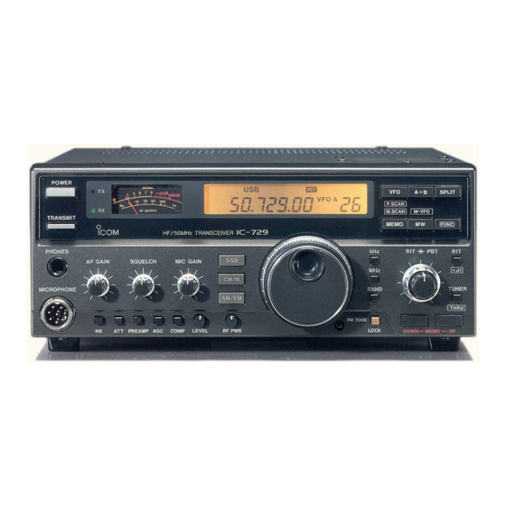
Icom IC-729 Instruction Manual (56 pages)
HF and Hf/50 MHz
Brand:
Icom
| Category:
Transceiver
| Size: 5.96 MB
Table of Contents
Table of Contents
2
Panel Description
3
Front Panel
3
Rear Panel
7
Technical Information
8
ACC Sockets
8
Function Display
9
Microphone
10
Microphone Connector
10
HM-12 Schematic Diagram
10
Installation and Connections
11
Unpacking
11
Mounting the Transceiver
11
Antenna
11
Connections Chart
12
HF Antenna
12
External Speaker
12
Ground
12
Power Supply Connections
13
Connecting an Icom DC Power Supply
13
Connecting a Non-Icom DC Power Supply
13
Linear Amplifier Connections
14
Connecting the IC-2KL
14
Connecting the IC-4KL
14
Connecting a Non-Icom Linear Amplifier
14
Antenna Tuner Connections
15
Connecting the AT-160
15
Connecting the AH-3
15
Connecting the AT-150
15
AFSK Terminal Unit Connections
16
Using the ACC Socket
16
Using the Microphone Connector
16
Remote Jack Information
17
Setting the CI-V Condition with the Diode Matrix
17
Baud Rate
17
Frequency Data
17
Transceive
18
Diode Location
18
Operation
19
Initial Settings
19
Basic Operation
19
Mode Types
20
VFO Mode
20
Memory Mode
20
Frequency Setting
21
For Ham Band Use
21
For General Coverage Receiver Use
21
Khz Tuning Step
22
Changing the Minimum Tuning Step
22
Auto Tuning Step Function
22
Receiving
23
SSB Receiving
24
CW Receiving
24
AM Receiving
24
FM Receiving
24
Transmitting
25
SSB Transmitting
26
CW Transmitting
26
AM Transmitting
26
FM Transmitting
26
RIT Function
27
PBT Operation
27
PBT Operation Example
27
Split Frequency Operation
28
Cross Mode Operation
28
Practical Example
28
Optional Antenna Tuner Operation
29
AH-3 Hf Automatic Antenna Tuner
29
AH-3 Operation
29
AT-160 HF Automatic Antenna Tuner
30
AT-160 Operation
30
Memory Channels
31
Memory Channel Selection
31
Selected Mode Memory Channel Selection
31
Memory Channel Programming
32
Programming in the VFO Mode
32
Programming in the the Memory Mode
32
Frequency Transferring
33
Transferring in the VFO Mode
33
Transferring in the Memory Mode
33
Programming Split Memory Channels
34
Split Memory Channel Selection
34
Split Memory Channel Programming
34
Split Memory Channel Operation
34
Scans
35
Scan Types
35
Pre-Operation
35
Memory Scan
35
Programmed Scan Operation
36
Memory Scan Operation
36
Selected Mode Memory Scan Operation
36
Maintenance and Adjustment
37
Disassembling the Transceiver
37
Removing Covers
37
Preparing for the PA Unit Removal
37
Removing the PA Unit
38
Opening the PA Unit
38
Removing the PLL Unit
38
Fuse Replacement
39
DC Power Cable Fuses Replacement
39
Circuitry Fuse Replacement
39
Resetting the CPU
39
Frequency Calibration
40
Main Dial Brake Adjustment
40
Cleaning
40
CW Side Tone Level Preset
41
Advanced Scan Functions
41
BFO Adjustment
41
RIT Adjustment
42
HF Bands PA Idling Current
42
PA Unit
42
Driver Transistors Idling Current
42
Options Installation
43
UI-7 AM/FM Unit
43
UT-30 Programmable Tone Encoder Unit
43
MB-23 Carrying Handle
43
FL-100 or FL-101 CW Narrow Filter
44
CR-64 High-Stability Crystal Unit
44
Troubleshooting
45
Inside Views
47
IC-728 Main Unit
47
IC-728 PLL Unit
48
IC-729 Main Unit
49
IC-729 PLL Unit
50
Specifications
51
Options
52
Advertisement
Icom IC-729 Service Manual (81 pages)
HF/50 MHz Transceiver
Brand:
Icom
| Category:
Transceiver
| Size: 14.48 MB
Table of Contents
Introduction
2
Ordering Parts
2
Repair Notes
2
Table of Contents
3
Specifications
4
General
4
Inside Views
5
Main Unit
5
PLL Unit
6
PA and Filter Units
6
Circuit Description
7
Receiver Circuits
7
HF Switching Circuit
7
HF Bandpass Filter Circuit
7
1St if Circuit
8
2Nd Mixer Circuit
8
Noise Blanker Circuit
8
2Nd if Circuit
8
3Rd Mixer and 3Rd if Circuits
9
BFO Circuit
9
PBT Circuit
9
BFO Frequency in each Mode
9
SSB/CW Demodulation Circuits
10
AM Demodulator Circuits
10
AF Input Mode Selector Switch
10
AGC Circuit
10
Transmitter Circuits
11
S-Meter Circuit
11
Squelch Circuit
11
AF Amplifier Circuit
11
FM and am Modulation Cricuits
12
CW Keying Circuit
12
IF Amplifier
12
RF Circuit
12
RF Meter Circuit
13
ALC Circuit
13
APC Circuit
13
PLL Circuits
14
Temperature Protection Circuit
14
1St lo PLL Circuit
14
Frequency Construction
14
Logic Circuits
15
Main Loop Circuit
15
Sub Loop Circuit
15
Reference Oscillator Circuit
15
Regulator Circuits
16
Cpu
16
Parallel/Serial Converter
16
RIT Control
16
Adjustment Procedures
17
Preparation before Servicing
17
Required Test Equipment
17
Connection
17
PLL Adjustment
18
PLL Unit and DDS Board
19
Receiver Adjustment
20
Transmitter Adjustment
24
PA, Filter and PB Units
25
Parts List
31
Front Part
31
SW Unit
31
AF Board
32
VR Board
32
PBT Board
33
MIC Board
33
Jack Unit
33
DDS Board
48
PA Parts
48
Mechanical Parts and Disassembly
52
Chassis Parts
52
PA Parts and Accessories
55
Accessories
56
Board Layouts
57
LED Board
57
FM/AM Unit
63
PA Unit
65
Filter Unit
66
PB Unit
67
Block Diagram
68
Voltage Diagrams
69
SW and Main Units
69
PLL and PA Units
74
Advertisement
Related Products
Icom IC-7200
ICOM IC-720
ICOM IC-726
Icom IC-725
Icom IC-728
Icom IC-720A
ICOM IC-746
Icom IC-706MKII
Icom IC-701
Icom IC-700
Icom Categories
Transceiver
Receiver
Repeater
Radio
Two-Way Radio
More Icom Manuals
Login
Sign In
OR
Sign in with Facebook
Sign in with Google
Upload manual
Upload from disk
Upload from URL