Sign In
Upload
Manuals
Brands
Icom Manuals
Transceiver
IC-211E
Icom IC-211E Manuals
Manuals and User Guides for Icom IC-211E. We have
1
Icom IC-211E manual available for free PDF download: Instruction Manual
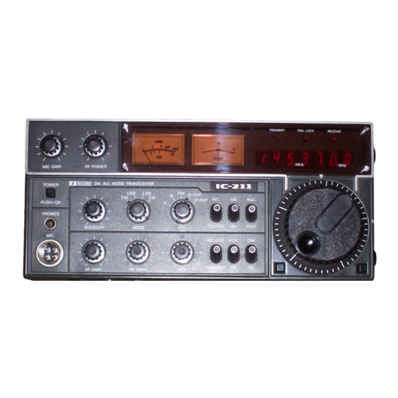
Icom IC-211E Instruction Manual (50 pages)
144MHz SSB FM CW Transceiver
Brand:
Icom
| Category:
Transceiver
| Size: 1.56 MB
Table of Contents
Table of Contents
2
Specifications
3
Description
5
Installation
6
Unpacking
6
Power Supply - for AC Operation
6
Antenna
7
External Speaker
7
Power Supply - for DC Operation
7
Headphones
8
Microphone
8
CW Key
8
Ground
8
Control Functions
9
Front Panel Facilities
9
Controls under Access Cover
13
Rear Panel Connections
14
Operation
16
How to Tune
16
Dial Lock Button
16
Tuning Speed Button
16
VFO Select Switch
17
N-Dup/R-Dup
18
RIT (Receiver Incremental Tuning)
19
SSB Operation
20
Receiving
20
NB (Noise Blanker)
20
AGC (Automatic Gain Control)
20
Transmitting
21
How to Use the VOX Circuit
21
CW Operation
22
CW Monitor
22
Semi Break-In Operation
22
FM Operation
22
VSWR Reading
24
For Satellite Communication Use
24
Frequency Chart
24
Connection of Accessory Socket
25
ACC Socket Connections
25
Inside Views
26
Theory of Operation
28
Receiver Circuits
28
RF Amplifier Circuits
28
Mixer Circuit
28
Noise Blanker Circuit
29
SSB if Amplifier Circuit
29
Detector Circuit
29
BFO Circuit/Agc Circuit
29
FM if Amplifier Circuit
30
Squelch Circuit
30
Transmitter Circuits
31
Audio Circuit
31
Microphone Amplifier Circuit
31
Balanced Modulator Circuit
31
10.7 Mhz Oscillator and FM Modulator Circuits
32
Transmit Mixer Circuit
32
Power Amplifier
32
Low-Pass Filter and SWR Detecting Circuit
32
APC Circuit
33
ALC and FM Power Control Circuits
33
VOX and CW Break-In Circuit
33
CW Monitoring Circuit
33
Power Supply Circuit
34
PLL (Phase Locked Loop) Unit
35
Local Oscillator Circuit
35
Mixer and Amplifier Circuit
35
PLL LSI Circuit
35
Loop Filter Circuit
36
D/A (Ditital to Analog) Converter Circuit
36
Transmit Muting Circuit
37
Logic Circuits
37
SL Control Circuit
37
X Control Circuit
38
Power Circuit
38
VCO Unit
38
Driver Unit
39
Photo-Chopper Circuit
39
Frequency Display
39
1Mhz Digit Display Truth Table
39
RIT Control Circuit
41
Photo-Chopper Circuit Schematic Diagram
41
Tone Call Unit
42
Dial Lock Circuit
42
Power Supply Unit
43
Troubleshooting
44
Block Diagram
47
PLL and Drive Circuits
48
Options
49
Advertisement
Advertisement
Related Products
ICOM IC-2100H
ICOM IC-211
Icom IC-2100-T
Icom IC-210
Icom IC-215
ICOM IC-207H
ICOM IC-2710H
ICOM IC-228H
ICOM IC-2iE
Icom IC-2410E
Icom Categories
Transceiver
Receiver
Repeater
Two-Way Radio
Radio
More Icom Manuals
Login
Sign In
OR
Sign in with Facebook
Sign in with Google
Upload manual
Upload from disk
Upload from URL