Sign In
Upload
Manuals
Brands
IceCure Manuals
Medical Equipment
IceSense3
IceCure IceSense3 Manuals
Manuals and User Guides for IceCure IceSense3. We have
2
IceCure IceSense3 manuals available for free PDF download: User Manual, Instructions For Use
IceCure IceSense3 User Manual (104 pages)
Brand:
IceCure
| Category:
Medical Equipment
| Size: 4 MB
Table of Contents
Table of Contents
2
1 Overview
7
Introduction
7
Intended Use
7
Indications for Use
7
Qualified Users
8
Clinical Decisions
9
Qualified Technician
9
2 Safety Notes
10
Warnings and Cautions
10
Basic Safety Principles
10
Ownership
10
Qualification
10
Training
11
Clarity
11
Clinical Assessment
12
Installation and Setup
13
Proper Use
14
Operating Warnings
15
Liquid Nitrogen
18
Danger - Explosion and Fire Hazard
18
Opening the Dewar Compartment
18
Voltage and Power Ratings
19
Liquid Nitrogen Safety
19
Burn Hazards
20
Grounding
21
Sterility
21
Mechanical Handling of Flexible Hose and Cryohandle
21
Emergencies and Errors
22
Emergency Stop Button
22
Emergencies Causing Procedure Halt
22
Adverse Events
23
Compliance
23
Compliance with International Safety Standards
23
Equipment Classification
23
Accompanying Labels
24
Figure 1: Label 1 - On/Off Mechanical Button - MLS1000002 Rev. B
25
Figure 2: Label 2 - Emergency Stop - MLS1000003 Rev. B
25
Figure 3: Label 3 - Identification - MLS3080001 Rev. F
25
Figure 4 Label 4 - Federal Laws Restriction - MLS1000004 Rev. B
25
Figure 5: Label 5 - Follow Instructions for Use - MLS1000005 Rev. C
26
Figure 6: Label 6 - High Voltage Caution - MLS1000006 Rev. B
26
Figure 7: Label 7 - Line Voltage Danger - MLS1000007 Rev. B
26
Figure 8: Label 8 - Foot Pedal - MLS1000008 Rev. B
26
Figure 9: Label 9 - Risk of Explosion - MLS1000009 Rev. B
26
Figure 10: Label 10 - Single Use Probe - MLP7000001 Rev. F
27
Figure 11: Label 11 - Single Use Temperature Sensor - MLT8000001 Rev. F
27
Figure 12: Label 12 - Liquid Nitrogen Dewar - MLS1000001 Rev. D
27
Figure 13 Label 13 - Cold Area - MLS1000010 Rev. B
28
Figure 14: Label 14- Empty LN2 Dewars - MLS1000012 Rev. a
28
Figure 15: Label 15- Applied Parts - MLS1000014 Rev. a
28
Figure 16: Label 16- Shipping Art Work
28
Important Symbols and Labels
29
3 System Description
32
Introduction
32
Concept of Operation
32
Major Components
32
Figure 17: Front and Back View of the Icesense3™ Cryoablation System with Numbered Components
32
Emergency Stop Button
33
Figure 18: the Icesense3™ Transportation Rollers & Brakes
33
Main Chassis
33
Figure 19: the Emergency Stop Button
34
Flexible Hose
34
Touch Screen
34
Cryohandle and Cryoprobe
35
Figure 20: the Touch Screen Display before a Cryoablation Procedure
35
Figure 21: the Flexible Hose, Cryohandle and Connected Cryoprobe
35
Figure 22: the 90 Degrees Cryohandle and Connected Cryoprobe
36
Handle Plug Holder
36
Figure 23: Handle Plug Holder and Handle Plug
37
Figure 24: the Foot Pedal
37
Foot Pedal (Not Available in some Regions, E.g. China)
37
Temperature Sensor (TS)
37
Figure 25: the Temperature Sensor and Its Components
38
Dewar Storage Cases
39
Figure 26: Temperature Display of Sensor in the Procedure Screen (Green Arrow)
39
Figure 27: Dewar Storage Cases - the Correct Way to Put the Dewars Inside the Storage
39
Operational Details
40
Starting the System
40
System Pre-Tests
41
Figure 28: the System Is Loading Screen
41
Figure 29: the Main Menu Screen
41
Cryoablation Procedure
42
Warm Step
42
4 Installation and Setup
43
Space and Positioning Requirements
43
Setup Warnings and Cautions
43
Electrical Requirements
44
Shipment Components
44
Installation
44
5 Operating the System
45
Procedure Overview
45
Pre-Operational Stages
45
Preparing the System for Procedure
45
Preparing the Patient for Procedure
45
Switching on the Icesense3™ Cryoablation System
46
Figure 30 : Schematic Illustration of Placement of the System and Patient
46
Figure 31: the System Is Loading Screen
47
Figure 32: the Main Menu Screen
47
Cryohandle
48
Show Last Treatment
48
Figure 33: the Action Button as Displayed on Screen (Several of the Options)
48
Figure 34: the Active Warm Button as Displayed on Screen
48
Figure 35: Last Treatment Screen
48
General Settings
49
Figure 36: Activating the Settings Option from the Main Menu Screen
49
Figure 37: the Settings Screen
49
Figure 38: the Change Workflow Screen with Two Alternative Workflow Settings
50
Preparing the System for Treatment
51
Figure 39: the Windows™ Date and Time Properties Screen
51
Figure 40: Preparing the System for Treatment by Pressing "Prepare for Treatment" (Green Arrow) on Main Menu Screen
52
Figure 41: the Dewar Preparation Screen
54
Figure 42: Experiments in Gel Results
54
Figure 43: the Cryoprobe (the Figure Is for Illustration Only)
55
Figure 44: Cryoprobe Registration Screen
55
Figure 45: Cryoprobe Connection Screen
56
Figure 46: Functional Test Screen
58
Figure 47: Functional Test - Visual Inspection Screen
59
Treatment Selection
60
Figure 48: Treatment Selection Screen
60
Figure 49: Define a Treatment Protocol by Choosing Edit Presets on the Treatment Selection
61
Figure 50: Editing an Existing Protocol (Green Arrow) or Adding a New One (Yellow Arrow)
61
Figure 51: Steps for Adding a Protocol
62
Figure 52: Edit Preset Screen
62
Operational Stages
63
Safe Operation in Percutaneous Procedures
63
Preliminaries
63
Figure 53: Choosing the Manual Mode Option (Green Arrow)
63
Freeze Cycle
65
Pause Option
66
Figure 55: Pause and Play Buttons During the Freeze Cycle
66
Manual Freeze Mode
67
Figure 56: Manual Mode Screen: Press on Freeze to Start the Freeze Cycle
67
Figure 58: Thaw Screen in Manual Mode
68
Figure 59: Warm Screen in Manual Mode
69
Thaw
70
Figure 60: Freeze Screen in Automatic Mode
70
Active Warm Process
71
Replace the Dewar During a Cryoprocedure
72
Figure 61: the Active Warm Screen During Procedure
72
Figure 62 : Replace Dewar Option Question
73
Figure 63: Lowering the Dewar
74
Figure 64: the Replace Dewar Screen and Press Ok to Continue
74
Figure 65: the Replacement Done Follow up Screen
75
Figure 66: Replacement was Completed before the Thaw Ended
76
Figure 67: Replacement was Completed after the Thaw Ended
77
Figure 68: Replacement During Freeze, in Case of Empty Dewar
77
Post-Operational Stages
78
Removing the Temperature Sensor from Tissue
78
Figure 69: Procedure Stopped Due to Low Nitrogen
78
Removing the Cryoprobe from the Cryohandle
79
Figure 70: Protocol Completed Screen
79
Disassembling the Temperature Sensor
80
Exiting the Icesense3™ Cryoablation System Treatment Mode
80
System Failures
81
Icesense3™ Cryoablation System Failure
81
Icesense3™ Cryoablation System Touch Screen Failure
81
6 Computer Interface
84
The Technician Menu
84
Reading the Screen
84
Parts of the Screen
84
System Messages
85
Status Messages
85
Warning Messages
85
Error Messages
86
7 Accessories
88
Cryoprobe
88
Single Use Sterile Cryoprobe
88
The Foot Pedal (Not Available in some Regions, E.g. China)
89
The Temperature Sensor
89
8 System Maintenance
90
General Cleaning
90
Sterility
90
Periodic Servicing
91
9 Troubleshooting
92
General
92
Troubleshooting Guide
92
10 Icesense3™ Cryoablation System - Step-By-Step Procedure
95
11 System Specifications
96
12 Temperature Distribution Analysis in Homogeneous Medium
97
13 Limited Warranty Certificate
98
14 Customer Complaint Form
99
15 Report Customer Complaint
100
16 Manufacturer's Declaration of the EUT
101
Advertisement
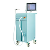
IceCure IceSense3 Instructions For Use (4 pages)
Cryoablation System
Brand:
IceCure
| Category:
Medical Equipment
| Size: 0 MB
Advertisement
Related Products
IceCure DSR3200000
IceCure ProSense
IceCure ProSense DMS-7063
IceCure ProSense FAS3000000
IceCure Categories
Medical Equipment
More IceCure Manuals
Login
Sign In
OR
Sign in with Facebook
Sign in with Google
Upload manual
Upload from disk
Upload from URL