Sign In
Upload
Manuals
Brands
IAI Manuals
Controller
Rcon
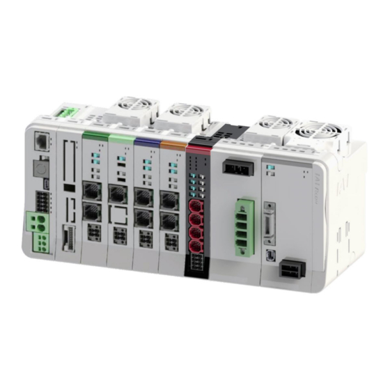
IAI Rcon Controller System Manuals
Manuals and User Guides for IAI Rcon Controller System. We have
2
IAI Rcon Controller System manuals available for free PDF download: Instruction Manual
IAI Rcon Instruction Manual (838 pages)
Brand:
IAI
| Category:
Controller
| Size: 51 MB
Table of Contents
Table of Contents
33
Chapter 1
34
Overview
34
Features
35
Field Network Control Operation Mode
37
List of Functions by Operation Mode
38
Operation of ELECYLINDER
40
General Specifications
41
Table of Contents
43
Chapter 2
46
System Configuration
46
Configuration Unit List
48
Specifications
52
General Specifications
52
Power Supply Capacity
55
Power on Sequence
61
Inrush Current
63
Operating Temperature Range
65
Installation Conditions
66
Unit Connection Restrictions
70
External Dimensions
72
Controller (24V Driver Unit 8-Axis Without Fan)
72
Controller (24V Driver Unit 8-Axis with Fan)
73
Controller (24V Driver Unit 16-Axis Without Fan)
74
Controller (24V Driver Unit 16-Axis with Fan)
75
Controller (200V Driver Unit 1-Axis with Fan)
76
Connection Diagrams
77
Power Supply and Stop Circuit / Drive Cutoff Circuit
77
Driver Stop Circuit
82
Motor/Encoder Circuit
88
AUTO/MANU Mode Switching Circuit Wiring
94
Field Network Wiring
95
Gateway Unit
101
Chapter 3
104
Overview
104
How to Read the Model Number
106
How to Read the Model Nameplate
107
Gateway Unit and Accessories
108
Part Names/Functions and External Dimensions
109
Part Names
109
LED Display
111
Ethernet Connector
112
AUTO/MANU Switch
112
SIO Connector
113
USB Connector
114
System I/O Connector
115
Motor Power Connector
116
Control Power Connector
117
Field Network Connector
118
Connectors
118
Terminal Unit
119
External Dimensions
120
Field Network General Specifications
122
CC-Link
122
CC-Link IE Field
123
Devicenet
124
Ethercat
125
Ethernet/Ip
126
Profibus-Dp
127
Profinet Io
128
Operation Function List
129
Field Network Control Operation Mode
129
List of Functions by Operation Mode
130
Operation of ELECYLINDER
132
Address Configuration
133
Overall Address Configuration Example
135
Gateway Control/Status Signals
146
Power Supply Unit (PSA-24) Status Signal
148
Position Table
151
Direct Numerical Control Mode Assignment
167
Simple Direct Mode Assignment
173
Positioner 1 Mode Assignment
177
Positioner 2 Mode Assignment
180
Positioner 3 Mode Assignment
181
Positioner 5 Mode Assignment
184
ELECYLINDER Position Table
187
Assignment of EC Connection Unit
190
I/O Signals
193
Timing of I/O Signals
193
Function of I/O Signals
194
Features of Input and Output Signals for EC Connection Unit
217
Caution When Connecting EC Connection Unit
220
Timing of Basic Operation
221
Other Basic Operations
230
Basic Operations of ELECYLINDER
246
Precautions for Rotary Type
251
Precautions for Gripper Type
254
Gateway Parameter Configuration Tool
256
Tool Startup
256
Menu Descriptions
257
Special Parameter Setting Function Descriptions
259
Explanations of Monitoring Menu Features
265
Operation Mode Setting
267
Operation Mode Individual Setting
269
Axis Number Assignment Change
270
Editing Driver Unit Configuration
271
Actuator Information Management Function
283
Overview
283
Actuators with Information Management Function Supported
284
Actuator Information Management Function
285
Parameters for Actuator Information Management Function Setting
288
Table of Contents
289
Chapter 4
292
Overview
292
How to Read the Model Number
294
How to Read the Model Nameplate
295
Components
296
Part Names/Functions and External Dimensions
298
[24V Driver Unit]
298
Part Names
298
LED Display
300
Jog Switch
301
Brake Release Switch
302
Motor/Encoder Connector
302
Drive Source Shutoff Connector
306
Fan Connector
307
Connectors
307
Fan Unit
308
External Dimensions (24V Driever Unit, Fun Unit)
310
[EC Connection Unit]
312
Part Names
312
LED Display
313
Brake Release Switch
315
Onnectors for EC Connection
316
Drive Source Shutoff Connector
317
Connectors
318
External Dimensions
319
Table of Contents
321
Chapter 5
324
Overview
324
How to Read the Model Number
326
How to Read the Model Nameplate
327
Components
329
Part Names/Functions and External Dimensions
331
[200V Driver Unit]
331
Part Names
331
LED Display
332
Jog Switch
333
Brake Release Switch
334
Motor Connector
334
Encoder Connector
335
Driver Stop Connector
336
Fan Connector
336
Connectors
336
Fan Unit for 200V Driver Unit
337
External Dimensions
339
[200V Power Supply Unit]
341
Part Names
341
External Regenerative Resistor Connector
344
AC Input Connector
345
Fan Connector
345
Connectors
346
Fan Unit
346
External Dimensions (200V Power Supply Unit, Terminal Unit)
348
Table of Contents
351
Chapter 6
352
Overview
352
How to Read the Model Number
354
How to Read the Model Nameplate
354
SCON Extension Unit and Components
355
Part Names/Functions and External Dimensions
356
Part Names
356
SCON Cable Connector
358
Connectors
359
External Dimensions
360
Table of Contents
361
Chapter 7
362
Overview
362
How to Read the Model Number
364
How to Read the Model Nameplate
365
Simple Absolute Unit and Components
366
General Specifications
367
Part Names/Functions and External Dimensions
371
Part Names
371
LED Display
372
Actuator Cable Connector/Driver Unit Cable Connector
372
External Dimensions
373
Precautions
374
Table of Contents
385
Installation
386
Requests/Precautions
386
Unit Connection
390
DIN Rail Mounting
391
Wiring
392
Controller Wiring
392
Actuator Wiring
397
CC-Link Wiring
400
Wiring for External Regenerative Resistor Unit
402
Table of Contents
405
Absolute Reset
406
Overview
406
Simple Absolute Unit Wiring
408
Parameter Setting
411
Absolute Reset Procedure
412
Absolute Battery
417
Precautions
419
Table of Contents
421
How to Use the Gateway Parameter Configuration Tool
422
Installing
422
RCON Setting: CC-Link (for Pic of PLC Wiring / Programming)
438
How to Connect Ethernet
447
Master Side Setting
450
PLC Setting: CC-Link (for Pic of PLC Wiring / Programming)
450
Installing PC Software
463
Installing
463
Address Configuration
467
Overall Address Configuration Example
469
Power Supply Unit (PSA-24) Status Signal
482
Operation Confirmation with PC Software
485
Operation Confirmation with PC Software
486
Home Return
495
Jog Travel
497
Position Travel
498
Operation Check of ELECYLINDER
501
Parameter
507
Parameter
508
Parameter List
508
Parameter Details
513
Parameter Details of ELECYLINDER
561
Servo Gain Adjustment
568
Various Functions
572
Vibration Damping Control Function
572
Collision Detection Function
579
Power-Saving Function
582
Simple Alarm Codes
617
(Pm8)
618
Alm Alm8
618
Alm1 (Pm1)
618
Alm2 (Pm2)
618
Alm4 (Pm4)
618
Binary Code
618
On ●: off
618
Position No. Error During Teaching
621
Position No. Error During Travel
621
PWRT Signal Detected While Traveling
621
Command Deceleration Error (0A7)
622
Position Command Information Data Error (0A3)
622
Z-Phase Position Error (0B5)
622
Z-Phase Detection Timeout (0B6)
623
Excitation Detection Error (0B8)
629
Advertisement
IAI Rcon Instruction Manual (140 pages)
SSCNET III/H Specifications, R-Unit
Brand:
IAI
| Category:
Gateway
| Size: 6 MB
Table of Contents
Please Read before Use
3
Safety Guide
10
Alert Indication
16
Precautions for Handling
17
International Standard Compliance
20
Table of Contents
21
Overview
22
System Configuration
23
Unit List
24
Model Code
28
Specifications
32
General Specifications
32
Power Capacity
34
Used Tools
35
RCON Motion Unit
38
Overview
38
Model Code
39
Components
40
Part Names/Functions
41
External Dimensions
51
Field Network Specifications
52
Specifications
52
Part Names
52
Status LED Display
53
Other Units
54
Driver Unit
54
Driver Unit, 200V Power Supply Unit
54
Extension Unit
54
Simple Absolute Unit
54
Installation
57
Installation and Mounting
57
Noise Countermeasures and Mounting Method
58
Wiring
60
Wiring of LC Unit Power Supply Connector
60
Power Supply Wiring to RCON Motion System
62
Actuator Connecting
64
Field Network Wiring
67
Setting
68
Contents for Gateway Parameter Setting
73
Parameter Configuration Tool for IAI Gateway Unit
75
Driver Unit Parameter Settings
80
Communication Flow
83
About Power Supply
84
Reserved
87
Alarm / Warning Number
88
Alarm Status
88
(AL20 to AL2F)
90
(AL40 to AL4F)
90
(AL60 to AL6F)
90
(AL80 to AL8F)
90
(ALE0 to ALEF)
90
Digit Display Number
90
Currently Being Occurred
90
It Makes a Feedback of a Detail
90
Number of the Driver Alarm
90
Described above
90
Transient Commands
93
About Parameters
99
Controller Parameters
100
Caution in Operation
114
Encoder Type
114
About Linear Spurious Absolute Type
115
Absolute Type
115
Availability in Absolute Position Detection System
115
About Home-Return
116
Home-Return Operation
116
Operation Alarms at Start of Home-Return Operation
117
Caution Regarding Home-Return Operation
118
About Control Specifications
119
Soft Limit Feature
119
Torque Control Features
120
Troubleshooting
121
About Alarms
123
Warranty
127
Warranty Period
128
Scope of the Warranty
128
Honoring the Warranty
128
Limited Liability
129
Conformance with Applicable Standards/Regulations, Etc., and Application Conditions
129
Other Items Excluded from Warranty
129
Revision History
137
Advertisement
Related Products
IAI RCON-FU
IAI RCON-ABU-A
IAI RCON-ABU-P
IAI RCON-EXT
IAI ROBO Cylinder RCP2-SS8C
IAI ROBO Cylinder RCP2-SA5C
IAI ROBO Cylinder RCP5-SA7C
IAI ROBO Cylinder RCP2W
IAI ROBO Cylinder RCS4-WRA14C
IAI ROBO Cylinder RCS4CR- SA4C
IAI Categories
Controller
Digital Camera
Gateway
Industrial Equipment
Security Camera
More IAI Manuals
Login
Sign In
OR
Sign in with Facebook
Sign in with Google
Upload manual
Upload from disk
Upload from URL