Sign In
Upload
Manuals
Brands
I-Gard Manuals
Protection Device
IPC DSP OHMNI
I-Gard IPC DSP OHMNI Manuals
Manuals and User Guides for I-Gard IPC DSP OHMNI. We have
1
I-Gard IPC DSP OHMNI manual available for free PDF download: Instruction Manual
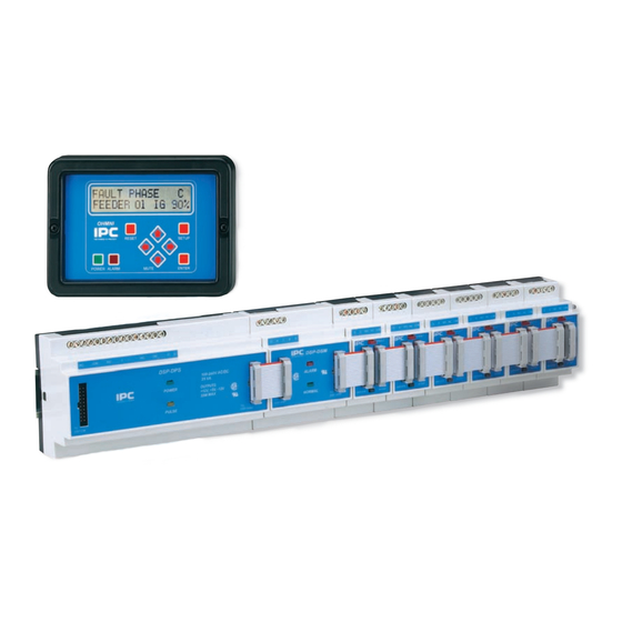
I-Gard IPC DSP OHMNI Instruction Manual (40 pages)
HIGH RESISTANCE GROUNDING SYSTEM
Brand:
I-Gard
| Category:
Protection Device
| Size: 0.94 MB
Table of Contents
Table of Contents
3
Table of Contents
5
Introduction
5
Application
6
Tables
7
Installation
7
Table 3.1 System Module Requirements
7
Table 3.2 Standard Ribbon Cables
7
Wiring
8
Figure 4.1A Typical One-Line Installation - Unit Substation
9
Figure 4.1C Power Supply DSP-DPS Wiring
9
Table of Figures
9
Figure 4.2 Preferred Feeder Module DSP-DFM Wiring
10
Figure 4.3 Alternative Sensor Wiring
10
Figure 4.4 Typical 4-Wire Communications Connection
11
Display
12
Figure 4.5 Alternative Two-Wire Connection for RS-485
12
Figure 5.1 Home Screen
12
Figure 5.2 Alarm Screen
12
Setup
13
Figure 6.1 Communications Set-Up
13
Figure 6.2 Communications Set-Up
13
Figure 6.3 Grounding Resistor Set-Up
14
Figure 6.4 Feeder Module Set-Up
14
Figure 6.5 I/D Check Indication
15
Figure 6.6 Feeder Module Set-Up
16
Figure 6.7 A) Feeder Module Successful B) Set-Up Not Successful
16
Figure 6.8 A) DSP-DM Allows Further Feeder Module Set-Up B) if Previous Set-Up Had Not Been Successful
16
Figure 6.9 Pulse Set-Up Request
17
Figure 6.10 Pulse Mode Set-Up
17
Figure 6.11 Typical Examples of Pulse Circuit Connection
18
Table 6.1 Pulsing Frequency Selection
19
Figure 6.12 Alarm Relay Setup
19
Figure 6.13 Alarm Relay Options
19
Operation
20
Figure 6.14 Save Screen
20
Figure 6.15 Self-Test Prompt
20
Figure 7.1 Normal Home Screen
20
Figure 7.2 System Leakage Current L
21
Figure 7.3 Feeder Current I
21
Figure 7.4 Trip Defeated
21
Alarm Indications
22
Figure 7.5 Pulse Control
22
Figure 7.6 New Home Screen Indicates Pulsing on
22
Figure 8.1 Alarm Screen
23
Self-Test
24
Figure 8.2 Bus Fault
24
Figure 9.1 System-Test Prompt
24
Figure 9.2 Prompt for Feeder Test
24
Events
25
Figure 9.3 Feeder Module Test
25
Figure 9.4 Test Result
25
Figure 10.1 Event Notification
25
Figure 10.2 Momentary Feeder Fault Example
25
Maintenance and Testing
26
Service
27
Communications
27
Table 13.1 MODBUS RTU Standard 8 Byte Holding Register Read Function (03)
28
Table 13.2 Returned Information Structure for Holding Register Request
28
Table 13.3 Request to Write to Set a Bit on a Register (Modbus Force Coil)
28
Table 13.4 Returned Information from Dsp Following a Force Bit Request
29
Table 13.5 Feeder Module Ground Current Addresses
30
Table 13.6 Feeder Module Status Addresses
31
Table 13.7 Feeder Module Priority Addresses
32
Specifi Cations
33
Table 13.8 System Function Registers
33
Outline Dimensions
35
Figure 15.1 DIN Rail Mounted Modules
35
Figure 15.2 DSP-DM Display Module with Cut-Out Detail
36
Figure 15.3 DSP-DPS Power Supply Connections
37
Figure 15.4 DSP-DSM System Module Connection
37
Figure 15.5 DSP-DFM Feeder Module Connection
37
Additional Information
38
Figure 15.6 DSP-DM Display Module Connections
38
Instruction Manuals Ibc
39
Advertisement
Advertisement
Related Products
I-Gard IPC GEMINI
I-Gard GCHK-100
I-Gard SENTINEL
I-Gard Categories
Protection Device
Relays
Industrial Electrical
Adapter
More I-Gard Manuals
Login
Sign In
OR
Sign in with Facebook
Sign in with Google
Upload manual
Upload from disk
Upload from URL