Sign In
Upload
Manuals
Brands
Hygood Manuals
Security Sensors
FM-200
Hygood FM-200 Manuals
Manuals and User Guides for Hygood FM-200. We have
1
Hygood FM-200 manual available for free PDF download: Installation Manual
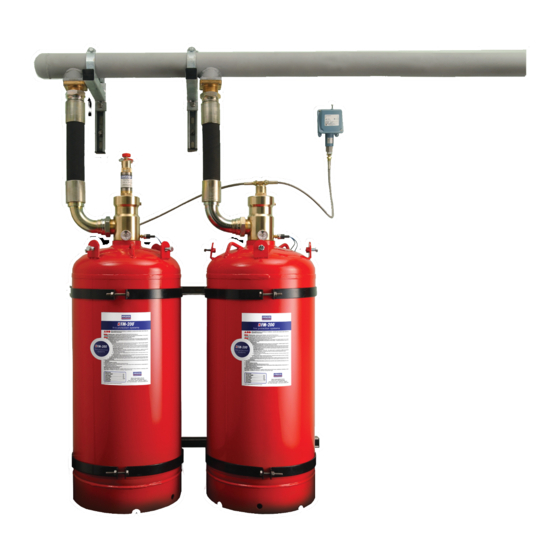
Hygood FM-200 Installation Manual (120 pages)
UL/FM VERSION TOTAL FLOOD FIRE SUPPRESSION SYSTEMS
Brand:
Hygood
| Category:
Security Sensors
| Size: 2 MB
Table of Contents
Table of Contents
2
Ul/Fm) 14A-07H
2
Section 1 - Introduction
5
About this Manual
5
Definitions
5
Contacts
5
Introduction
5
Approvals and Standards
5
FM-200® Agent
6
Manufactured Systems
6
Health and Safety
6
First Aid
7
FM-200® Agent Characteristics
7
Agent Physical Properties
8
Section 2 - System Components
9
System Components
9
FM-200® Container
9
Lengths
10
Container Label
11
Valve Assembly
12
Principle of Operation
13
Burst Disc
13
Low Pressure Switch (Standard Open on Fall)
14
Low Pressure Switch (Special Close on Fall)
14
Low Pressure Switch
14
Fall - Option #1)
15
Low Pressure Switch
15
Fixing Brackets
16
Manual Actuator
17
Pneumatic Actuator
17
Removable Electrical Actuator
18
Diode)
18
Removable Electrical Actuator (Bridge Rectifier)
18
Hose
19
MM (3") Discharge Hose/Check Valve
20
Assembly
20
0 MM ( 3") Discharge Hose
20
0 MM ( 3") Valve Single Tank Adaptors
21
Manifold Check Valve
21
Manifold
22
Manifold Inlets (Sockets)
24
Table 7: Manifold Inlets
24
Construction of Manifolds
25
Manifold Bracket Assembly
27
Flexible Pilot Hose
27
Male Adaptors
28
Male Pilot Hose Connector
28
Street Elbow
29
Male Tee
29
Male Elbow
30
Pressure Switch
30
Discharge Nozzle
31
Table 9: Discharge Nozzles
32
Door Notice
33
Manual Release Notice
33
Liquid Level Measuring Device
34
Typical Manifold System
35
Section 3 - System Design
36
System Design
36
Hazard Analysis
36
Hazard Structure
37
Hazard Volume
37
Ventilation
38
Hazard Temperature
38
Hazard Fuels
38
Personnel Safety
38
Agent Quantities
38
Agent Storage
38
Manifolds
39
Agent Distribution
39
Agent Flow Characteristics
40
Nitrogen Superpressurisation
40
Flow in Pipe
40
Initial Vapour Discharge
40
Trailing Vapour Pressure
40
Nozzle Selection and Location
40
Maximum Limits (Elevation) in Pipe Work
41
Nozzle Discharge Radius
42
Example: Nozzle Selection
42
System Design Procedure
42
Example: Tee Split Designs
43
Design Example - Calculations
44
Example
44
Piping Practices
46
Introduction
47
Imperial
48
Section 4 - Flow Calculations
49
FM-200® Equation Calculations
49
Engineered Systems
49
Program Parameters
49
Components
50
Table 14 : Equivalent Length for Pipe Fittings
50
Section 5 - Installation
51
General Information
51
Container Installation
51
Single Container Installation
52
Multiple Container Installation
54
Manifold Bracket Installation
54
Table 17: Manifold Bracket Fixing Heights
55
Pipe Installation
56
Pipe Hangers
57
Table 20: US Steel Pipe Requirements
57
Earthing and Electrical Clearance
58
Nozzles
58
Actuation Installation
59
Single Container Actuation
59
Multiple Container Actuation
61
Ancillary Equipment
63
Discharge Pressure Switch
63
Discharge Pressure Switch Continued
64
Low Pressure Switch
64
Accessories
64
Door Notices
64
Manual Release Notices
64
Completion Procedures
64
Pre-Checks and Visual Inspections
65
Final Connections
65
Hand-Over Procedures
66
Section 6 - Integrity Testing
67
Introduction
67
Principle
67
Equivalent Leakage Area (ELA)
67
Below Ceiling Leakage Area (BCLA)
67
Predicting Retention Time
67
Slab to Slab Walls
67
Coordination and Planning
67
Integrity Test Procedure
68
Enclosure Evaluation
68
Calculation
69
Leakage Location
69
Section 7 - System Operation
70
General Comments
70
System Detection and Actuation
70
General
70
Manual System
70
Fully Automatic System
70
Vention
71
Conditions During a Fire
71
FM-200® Concentration
71
FM-200® Decomposition
71
FM-200® Discharge Conditions
71
Actions Following a Fire
72
General
72
Actions Immediately Following a Fire
72
Section 8 - Maintenance
73
Introduction
73
User's Programme of Inspection
73
Contract Service and Maintenance
74
Mechanical Servicing Procedure
77
Specialised Maintenance Duties
77
Finally
77
Section 9 - Recharging Procedure
78
Recharging (O
78
Valve Refurbishment (O
78
Testing (O
81
Replacing Valve Assembly to Container
81
Field Installing Liquid Level Measuring Device
82
Filling
82
Table 24 :Fill Tolerance Table
83
Container / Valve Assy Leakage Test
85
Container Leak Test
85
Section 10 - Warranty, Disclaimers & Limitations
86
Warranty
86
Disclaimers and Limitations
86
Section 11 - Appendices
87
APPENDIX A - Temperature Correction Chart
88
APPENDIX B - Hughes Program Printout
89
Material Safety Data
100
APPENDIX C - FM-200 Material Safety Data
100
Sheet (MSDS)
100
APPENDIX D - FM-200 ® Liquid Level
106
Indicator Charts
106
Advertisement
Advertisement
Related Products
Hygood Categories
Security System
Fire Extinguisher
Security Sensors
More Hygood Manuals
Login
Sign In
OR
Sign in with Facebook
Sign in with Google
Upload manual
Upload from disk
Upload from URL