Sign In
Upload
Manuals
Brands
hyfire Manuals
Control Panel
Hy-Go/66
hyfire Hy-Go/66 Manuals
Manuals and User Guides for hyfire Hy-Go/66. We have
1
hyfire Hy-Go/66 manual available for free PDF download: Product Manual
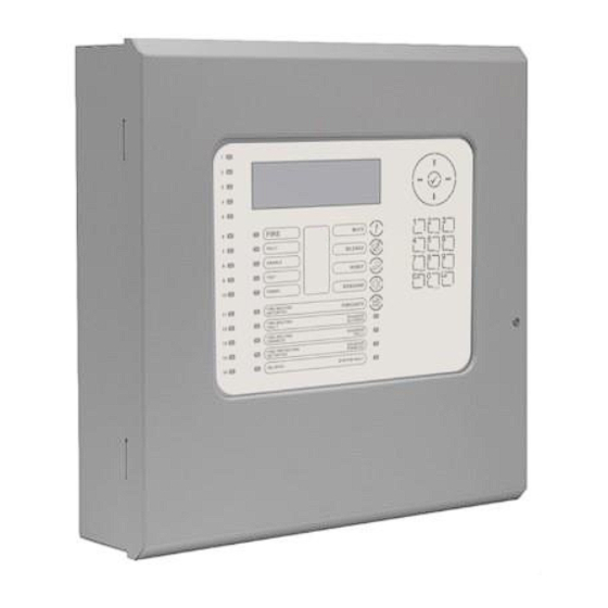
hyfire Hy-Go/66 Product Manual (110 pages)
Fire Alarm Control Panels
Brand:
hyfire
| Category:
Control Panel
| Size: 3 MB
Table of Contents
Table of Contents
3
Standards
9
En54-2: 1997 + A1:2006
9
En54-4: 1997 +A1:2002 +A2:2006
10
Low Voltage Directive 2014/35/Eu
10
Electromagnetic Compatibility Directive 2014/30/Eu
10
En54 Optional Features with Requirements
10
Outputs to Fire Alarm Devices (Section 7.8)
10
Outputs to Fire Routing Equipment (Section 7.9)
10
Outputs to Fire Protection Equipment (Section 7.10)
10
Delays to Outputs (Section 7.11)
11
Coincidence Detection (Section 7.12)
11
Alarm Counter (Section 7.13)
11
Fault Signals from Points (Section 8.3)
11
Outputs to Fault Routing Equipment (Section 8.9)
11
Disablement of Points (Section 9.5)
11
Test Condition (Section 10)
11
Safety Precautions
13
General
13
Precautions
13
Introduction
15
Description
15
Hy-Go Series
15
Hy-Go Series Protocol
15
Figure 1 - Hy-Go Fire Alarm Control Panel
15
Specifications
16
Installation
17
Installation Approvals
17
Fire System Installations
17
Wiring Regulations
17
Part Location
18
Install the Panel
18
Open the Enclosure Cover
18
Figure 2 - Hy-Go Part Location
18
Remove the Chassis
19
Figure 3 - Chassis Remove/Install
19
Mount the Back-Box
20
Install the Chassis
20
Figure 4 - Back-Box Enclosure
20
Recommended Cable Routing
21
Peripheral Bus (Pbus) Modules
21
Figure 5 - Recommended Routing
21
Figure 6 - PBUS Assembly
21
PBUS Adaptor Card GOP-001
22
Figure 7 - Peripheral Bus Adaptor Location
22
Routing Interface Card MXP-532
23
Figure 8 - Connect the PBUS Adaptor Card
23
Wiring Installation
24
Figure 9 - Install the Routing Card
24
AC Mains Wiring
25
Cable Glands
25
Figure 10 - AC Mains Terminations
25
Battery Installation
26
Mounting the Batteries
26
Battery Connection
26
Figure 11 - Battery Mounting
26
Detector Loop Installation
27
Figure 12 - Battery Wiring
27
Figure 13 - Base Card Detector Terminations
28
Figure 14 - a Simple Detector Loop
28
Sounder Circuits
29
Figure 15 - Base Card Sounder Terminations
29
Figure 16 - Simple Sounder Circuits a and B
29
Figure 17 - Sounders with Active EOL
30
Relay Circuits
31
Figure 18 - Basecard Relay Outputs
31
Peripheral Bus Interface
32
Switch Inputs
32
Figure 19 - PBUS Adapter Card
32
USB Interface (Type B)
33
Ethernet Interface
33
Routing Interface MXP-532
33
Figure 20 - Optional Key Switch
33
Figure 21 - Routing Interface Card
33
Fire/Fault Routing
34
Figure 22 - Routing Interface Card, Typical Arrangement
34
Fire Protection Routing
35
Figure 23 - Fail Safe Arrangement
35
Figure 24 - Fire Protection Routing
35
Programming
37
Introduction
37
Access Levels
37
Memory Lock
37
Figure 25 - Memory Lock (Unlock Shown)
37
Navigating through Menus
38
Changing Text Descriptions
38
Numeric Data Entry
39
Level 3 Menu Functions
40
Recommended Programming Procedure
41
Loops - View/Edit
41
Address
41
State
41
Type
41
Value
42
Zone
42
Device Text
42
Action
42
Sensitivity
43
O/P Group
45
Additional Info
45
Device Testing
45
Loops - Auto Learn
46
Normal Procedure/Initial Learn
46
Procedure if the Panel Finds a Missing Device
46
Procedure if the Panel Finds Devices Added
47
Procedure if the Panel Finds Devices Changed
47
Loop - Calibrate
47
Loop - History
48
Loop - Meter
48
Zones
49
Exit
49
Disable
50
Enable
50
View Options
50
Passwords
50
Time and Date
51
PC Config
51
En54-13
51
Setup
52
Panel Zone
52
Service Number
52
Service Due Date
52
Trace Logging Mode
53
Detector Blinking
53
Earth Fault Notification
54
Resound
54
Config Data
54
Display
54
Panel
55
AC Fail Delay
55
Output Groups
56
Default Output Settings
57
Cause
57
Style
58
Delay
59
Mode
59
Wait
59
Copying Output Settings to Multiple Zones
59
Investigation Delays
59
Overriding Delays at Level 1
60
Test
60
LED Indications
60
Operation
61
Access Levels
61
Changing from Access Level 1 to Level 2
61
Menu Access
61
Control Buttons at Level 1
62
Changing from Access Level 2 to 1
62
Controls and Indications
63
Graphical Display
63
Figure 26 - Hy-Go Front Panel Controls
63
LED Status Indicators
64
Zone LED Status Indicators
64
Control Buttons
64
Navigation Buttons
65
Number and Letter Buttons
65
Buzzer
65
Fire Alarm Condition
66
Investigation Delays
67
Fault Condition
67
Disablement Condition
69
Disabled Inputs
69
Disabled Outputs
70
Alarm Condition
71
Supervisory Condition
71
Multiple Conditions
71
Menu Functions
72
Using the Buttons to Navigate Menus
73
Selecting Menu Options
73
Selecting Individual Zone Numbers
73
Viewing
74
View - Fires
74
View - Faults
74
View - Alarms
75
View - Disabled
75
View - Inputs
75
View - Outputs
75
View - Panel
76
Software
76
Local Hardware
77
View - Log
78
Event Log
79
Alarm Counter
79
View - Warnings
79
View - Supervisory
80
Disabling
80
Disable - Zones and Inputs
80
Disable - Outputs
81
All Sounder Outputs
82
All Beacon Outputs
82
Fire Routing Outputs
82
Fire Protection Outputs
82
Fault Routing Outputs
82
All Other Relay Outputs
82
Selected Outputs
82
Disable - Controls
83
Disable - User ID
83
Disable - Groups
84
Enabling
85
Enable - Zones and Inputs
85
Enable - Outputs
85
Enable - Groups
85
Enable - Remote
85
Delays
86
Turn off Delay Mode
86
Turn on Delay-Mode
87
Extend Delays
87
Holiday/Inhibit
87
Testing
88
Test - Zones
88
Test - Display
90
Test - Buzzer
90
Test - Outputs
90
Tools
91
Change-Time
91
Service and Maintenance
93
Maintenance Schedule
93
Daily Actions
93
Monthly Actions
93
Quarterly Actions
93
Annual Actions
93
Replacement of Components
94
Batteries
94
Standby Batteries
94
Spares
95
Appendices
97
Appendix 1 - Forgotten Level 3 Password
97
Appendix 2 - Recommended Fire Rated Cables
99
Detector Loop Lengths -Argus
100
Sounder Circuit Lengths
100
Fire/Fault Routing Circuit Lengths
101
Appendix 3 - Battery Standby Calculation Chart
103
Appendix 4 - Cause and Effect Programming Example
105
Introduction
105
Output Groups
105
Styles
105
Output Group Programming
106
Appendix 5 - Other Useful Documents
107
Appendix 6 - Hy-Go Product Capabilities/Max Limits
109
Advertisement
Advertisement
Related Products
hyfire Hy-Go/240
hyfire HY5000 Series
hyfire HY-5100
hyfire HY-5200
hyfire HY-5400
hyfire HY5000R
hyfire HFW-STK-03
hyfire HFC-SBR-23-03
hyfire HFW-SIM-01
hyfire HFC-WSR-03
hyfire Categories
Security Sensors
Marine Equipment
Security System
Control Unit
Extender
More hyfire Manuals
Login
Sign In
OR
Sign in with Facebook
Sign in with Google
Upload manual
Upload from disk
Upload from URL