Sign In
Upload
Manuals
Brands
Hubner Manuals
Media Converter
AMP 41
User Manuals: Hubner AMP 41 Absolute Encoder
Manuals and User Guides for Hubner AMP 41 Absolute Encoder. We have
1
Hubner AMP 41 Absolute Encoder manual available for free PDF download: Operating And Assembly Instructions Manual
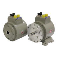
Hubner AMP 41 Operating And Assembly Instructions Manual (106 pages)
Absolute encoder with PROFIBUS-DP interface and PROFIsafe protocol
Brand:
Hubner
| Category:
Media Converter
| Size: 5 MB
Table of Contents
Table of Contents
4
Revision Index
8
1 General Information
9
Applicability
9
General Functional Description
9
Main Features
10
Principle of the Safety Function
10
Applied Directives and Standards
11
Overview of the Complete System
13
2 Basic Safety Instructions
14
Explanation of Symbols and Notes
14
General Risks When Using the Product
15
Intended Use
15
Non-Intended Use
15
Safety Functions of the Fail-Safe Processing Unit
16
Mandatory Safety Checks / Measures
16
Warranty and Liability
17
Organizational Measures
17
Personnel Selection and Qualification; Basic Obligations
17
Safety Information
18
3 Transport, Packaging and Storage
19
Safety Instructions for Transport
19
Incomings Goods Inspection
19
Packaging / Disposal
19
Storage of Packages (Devices)
19
4 Assembly
20
Safety Instructions and Requirements
20
Technical Notes
21
Required Tools
21
Mounting Preparations
21
Mounting of AMP 41, Construction Type B5 (Flange)
22
Mounting of AMP 41, Construction Type B35 (Flange and Foot)
23
Mounting of AMPH 41, (Hollow Shaft Type)
24
Dismantling of AMPH 41
25
5 Installation / Preparation for Commissioning
26
Basic Rules
26
PROFIBUS Transfer Technology, Cable Specification
27
Connection
28
Supply Voltage
28
Profibus
29
Incremental Interface
29
Optional External SSI Safety Channel
29
Bus Termination
29
Bus Addressing
30
Incremental Interface
30
Signal Characteristics of Incremental Interface
31
Option HTL-Level, 13
32
6 PROFIBUS / Profisafe - Commissioning
33
Profibus
33
DP Communication Protocol
34
Device Master File (GSD)
34
PNO ID Number
35
Profisafe
35
Measuring System PROFIBUS / Profisafe Communication
35
Start-Up on PROFIBUS
37
Bus Status Display
38
Configuration
39
Safety-Oriented Data, JHG-Profisafe Module
39
Register Structure of Safety-Oriented Data
40
Input Data
40
Cam Register
40
Status
40
Speed
40
Multi-Turn / Single-Turn
41
Safe-Status
41
Output Data
43
Control1
43
Control2
43
Preset Multi-Turn / Preset Single-Turn
43
Safe-Control
44
Process Data, JHG-PROFIBUS Module
45
Register Structure of the Process Data
45
Input Data
45
Cam Register
45
Speed
45
Multi-Turn / Single-Turn
46
Parameterization
46
F-Parameters (F_Par)
47
F_Check_Seqnr
47
F_Sil
47
F_Crc_Length
47
F_Block_Id
48
F_Par_Version
48
F_Source_Add / F_Dest_Add
48
F_Wd_Time
48
F_Ipar_Crc
48
F_Par_Crc
49
Iparameters (F_Ipar)
49
Integration Time Safe
50
Integration Time Unsafe
50
Window Increments
50
Idleness Tolerance Preset
50
Direction
50
7 Parameter Definition/Crc Calculation
51
Iparameters
51
CRC Calculation Across the Iparameters
51
F-Parameters
53
Non-Settable F-Parameters
53
Settable F-Parameters
53
8 Safety Creation - Configuration Example
55
Prerequisites
55
Hardware Configuration
56
Defining the Properties of the Hardware Configuration
61
Parameterization
66
Setting the Iparameters
66
Setting the F-Parameters
67
Creating the Missing (F-)Blocks
68
Program Structure
68
F-Runtime Group
68
Generating the Object Blocks (Obs)
69
Generating the Functions (F-Fcs)
70
Programming the F-Blocks
71
Generating the Safety Program
73
Loading the Safety Program
74
Testing the Safety Program
74
9 Access to the Safety-Oriented Data Channel
74
Output of Passivated Data (Substitute Values) in Case of Error
75
F-Periphery-DB
75
Measuring System F-Periphery-DB "DB1638" - Overview of Variables
76
Pass_On
76
Ack_Nec
76
Ack_Rei
77
Ipar_En
77
Pass_Out/Qbad/Qbad_I_Xx/Qbad_O_Xx
77
Ack_Req
77
Ipar_Ok
78
Diag
78
Access to Variables of the F-Perhiphery-DB
78
Passivation and Operator Acknowledgment of the Measuring System
79
After Start-Up of the F-System
79
After Communication Errors
79
10 Preset Adjustment Function
80
Procedure
81
11 Troubleshooting and Diagnosis Options
82
Optical Displays
82
LED, Green
82
LED, Red
83
Use of the PROFIBUS Diagnosis
84
Standard Diagnosis
84
Station Status 1
85
Station Status 2
85
Station Status 3
85
Master Address
85
Manufacturer's Identifier
86
Length (in Bytes) of the Extended Diagnosis
86
Extended Diagnosis
86
12 Replacing the Measuring System
87
13 Checklist
88
14 Technical Data
89
Safety
89
Electrical Characteristics
89
General
89
Device-Specific
90
Environmental Conditions
91
Mechanical Characteristics
91
Amp 41
91
Amph 41
92
15 Maintenance
93
16 Appendix
94
References
94
Abbreviations and Terms Used
94
TÜV Certificate
96
PROFIBUS-DP Certificate
97
Profisafe Certificate
98
Accessories
99
Dimension Drawings
100
AMP 41, Construction Type B5 (Flange)
100
AMP 41 Construction Type B35 (Flange and Foot)
101
AMPH 41 (Hollow Shaft Design)
102
AMPH 41 with Adapter Shaft ADA HFA (External Centering)
103
AMPH 41 with Adapter Shaft ADA HG (Screw-In Type)
104
Type Plate
105
Type Code
106
Advertisement
Advertisement
Related Products
Hubner AMPH 41
Hubner AMSH 40 K-1312
Hubner ASSH 40 K-13
Hubner Baumer FSL
Hubner Baumer POG 90
Hubner Cobolt Tor XE
Hubner ECU C
Hubner EGS C-R
Hubner ERC C-R
Hubner ERC40
Hubner Categories
Media Converter
Measuring Instruments
Switch
Control Unit
Portable Generator
More Hubner Manuals
Login
Sign In
OR
Sign in with Facebook
Sign in with Google
Upload manual
Upload from disk
Upload from URL