Sign In
Upload
Manuals
Brands
HT Italia Manuals
Measuring Instruments
GSC57
HT Italia GSC57 Manuals
Manuals and User Guides for HT Italia GSC57. We have
1
HT Italia GSC57 manual available for free PDF download: Instruction Manual
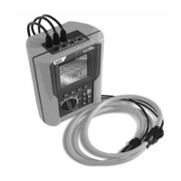
HT Italia GSC57 Instruction Manual (152 pages)
Brand:
HT Italia
| Category:
Measuring Instruments
| Size: 7 MB
Table of Contents
Table of Contents
3
Safety Precautions and Procedures
6
General
6
Preliminary Instruction
6
During Use
7
After Use
7
General Description
8
Introduction
8
Functions
8
Preparation for Use
10
Initial Control
10
Power Supply
10
Calibration
11
Storage
11
Instrument Description
12
Display Description
13
Initial Screen
13
Backlight Function
13
Initial Settings
14
How to Adjust the Contrast
14
How to Set Date and Time
14
How to Set the Language
14
Reset
15
Safety Test Functions
16
LOW : Continuity Test with 200Ma Test Current
16
Calibrating the Test Leads ("CAL" Mode)
17
Procedure to Reset Test Leads' Calibration Parameters
18
Measurement Procedure
19
Results of "AUTO" Mode
20
Results of "RT+" and "RT-" Modes
20
AUTO", RT+", "RT-" Faulty Cases
21
M : Insulation Resistance Measurement with 50V, 100V, 250V, 500V, 1000V Test Voltage
23
Measurement Procedure
23
Results of "MAN" Mode
25
Results of "TMR" Mode
26
MAN" and "TIMER" Mode Faulty Cases
27
RCD: Test on "A" and "AC" Rcds Type
28
Tripping Times for the General and Selective Rcds
30
Measurement Procedure
31
Results of "X½" Mode
32
Results of "X1, X2, X5" Mode
33
Results of "AUTO" Mode
34
Results of "RAMP " Mode
35
Results of " R a " Mode
36
RCD Faulty Cases
37
Connection Troubles
37
RCD Tripping "Faulty Cases
39
Loop
42
Calculation and Phase Sequence Indicator
42
High Resolution Impedance Measurement (0.1M )
42
Measurement Procedure and Results of "P-N" Mode
43
Measurement Procedure and Results of "P-P" Mode
45
Measurement Procedure and Results of "P-PE" Mode
47
Measurement Procedure and Results of " R
49
A " Mode
49
Measurement Procedure and Results of " " Mode
51
LOOP Faulty Cases
52
EARTH: Soil Resistance and Resistivity Measurements
57
Measurement Procedure and Results of "2-W"And "3-W" Mode
58
Measurement Procedure and Results of " " Mode
60
2-W", "3-W" and " " Faulty Cases
61
LOW10A: Continuity Test with 10A Test Current (GSC57 ONLY)
64
Measurement Procedure and Result of "RMEAS" Mode
65
Measurement Procedure and Result of "VDROP" Mode
66
RMEAS" and "VDROP" Faulty Cases
67
Aux: Measurement with External Probes
69
Environmental Parameter and Leakage Current: Real Time Measurement
70
Environmental Parameter and Leakage Current: Recording
72
AUX Basic Setting: RECORDER CONFIG
72
RECORDING: Setting of Typical Configurations
74
Analyser
75
Basic Setting: ANALYSER CONFIG
76
How to Set the Type of Electrical System under Test
76
How to Set the Fundamental Frequency
76
How to Set the Current Range
76
How to Set the Clamp Type
77
How to Set the Value of the Transformer Voltage Ratio (TV RATIO)
77
How to Enable/Disable the Password
77
Basic Setting: RECORDER CONFIG
78
Analyser Functions
85
VOLTAGE" Function
86
Symbols
86
METER" Mode
87
HARM" Mode
88
WAVE" Mode
89
CURRENT" Function
90
Symbols
90
METER" Mode
91
HARM" Mode
92
WAVE" Mode
93
POWER" Function
94
Symbols
94
METER" Mode
95
Peak Energy Demand
96
WAVE" Mode
97
ENERGY" Function
98
Symbols
98
METER" Mode
99
Measuring Procedures
100
Using the Instrument in a Single Phase System
100
Using the Instrument in a Three Phase 4 Wire System
101
Using the Instrument in a Three Phase 3 Wire System
103
Saving Results
105
Saving Safety Test Results
105
Saving Displayed Values of ANALYSER Function
105
Recordings
106
Start a Recording
106
Setting Typical Configurations
107
Default Configuration
107
Typical Configurations
108
During a Recording
112
MENU Key
112
Rotary Switch During a Recording
113
Stopping a Recording or an Energy Measurement
114
Instrument's Memory
115
Safety Test Memory
115
Analyser Memory
116
Connecting the Instrument to a Pc
117
Connection through Bluetooth Protocol
117
Maintenance
118
General Instruction
118
Battery Replacement
118
Instrument Cleaning
118
End of Life
118
Technical Specifications
119
Technical Features
119
Safety Test Functions
119
ANALYSER and AUX Functions
121
Standards
122
General
122
Emc
122
Safety Test
122
Analyser
122
General Specifications
123
Mechanical Data
123
Power Supply
123
Display
123
Memory
123
Environment
123
Accessories
124
Service
126
Warranty Conditions
126
Practical Reports for Electrical Tests
127
Continuity Test on Protective Conductors
127
Insulation Resistance Measurement of the Electrical Installations (250Vdc, 500Vdc, 1000Vdc)
129
Check of the Circuit Separation
132
Earth Resistance Measurement in TT Systems
135
Working Test of Rcds (Rcd, Rcd/DC, Rcd S, Rcd/DC S)
136
Test of Rcd Tripping Time (Rcd, Rcd/DC)
137
Measurement of Short-Circuit Fault Impedance
138
Pn Pp
138
Fault Loop Impedance Measurement (Phase - Earth)
138
Earth Resistivity Measurement
139
Voltage Anomalies (Voltage Sag and Surge)
141
Voltage and Current Harmonics
141
Theory
141
Limit Values for Harmonics
143
Presence of Harmonics: Causes
143
Presence of Harmonics: Consequences
144
Power and Power Factor Definition
144
Conventions on Powers and Power Factors
146
Phase 3 Wire System
147
Measuring Method: Outlines
148
Integration Periods
148
Power Factor Calculations
148
Appendix 1 - Messages Displayed
149
Appendix 2 - Recordable Parameters: Symbols
150
Advertisement
Advertisement
Related Products
HT Italia GSC53N
HT Italia GEO416
HT Italia GEO416GS
HT Italia COMBI521
HT Italia HT2234N
HT Italia HT3320
HT Italia HT52
HT Italia HT52/05
HT Italia HT53
HT Italia HT53/05
HT Italia Categories
Measuring Instruments
Multimeter
Test Equipment
Thermal cameras
Data Loggers
More HT Italia Manuals
Login
Sign In
OR
Sign in with Facebook
Sign in with Google
Upload manual
Upload from disk
Upload from URL