Sign In
Upload
Manuals
Brands
HPC Manuals
Air Compressor
MOBILAIR M27 PE
HPC MOBILAIR M27 PE Manuals
Manuals and User Guides for HPC MOBILAIR M27 PE. We have
1
HPC MOBILAIR M27 PE manual available for free PDF download: Operating Manual
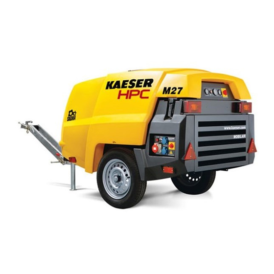
HPC MOBILAIR M27 PE Operating Manual (312 pages)
Portable Rotary Screw Compressor
Brand:
HPC
| Category:
Air Compressor
| Size: 22 MB
Table of Contents
Table of Contents
3
Regarding this Document Using this Document
13
Further Documents
13
Copyright
13
Symbols and Labels
13
Warnings
13
Tab. 1 Danger Levels and Their Definition (Personal Injury)
13
Potential Damage Warnings
14
Other Alert Notes and Their Symbols
14
Tab. 2 Danger Levels and Their Definition (Damage to Property)
14
Technical Specifications Nameplate
16
Vehicle Identification Number
16
Options Overview
16
Tab. 3 Nameplate
16
Air Treatment
17
Tool Lubricator
17
Compressed Air Distributor
17
Fig. 1 Option Label MOBILAIR M27 PE with Options
17
Tab. 4 Air Treatment Options
17
Tab. 5 Tool Lubricator Option
17
Proportional Controller
18
Non-Return Function
18
Low Temperature Equipment
18
Equipment for Fire Hazard Areas
18
Tab. 6 Compressed Air Distributor Option
18
Tab. 7 Proportional Controller Options
18
Tab. 8 Non-Return Option
18
Tab. 9 Low Temperature Equipment Options
18
Tab. 10 Optional Equipment for Fire Hazard Areas
18
Fuel De-Watering Filter
19
Battery Isolating Switch
19
Generator
19
Chassis
19
Tab. 11 Fuel De-Watering Filter Option
19
Tab. 12 Optional Battery Isolating Switch
19
Tab. 13 Generator Option
19
Lighting
20
Sealed Floor Pan
20
Hose Reels
20
Anti-Theft Device
20
Tab. 14 Chassis Options
20
Tab. 15 Lighting Options
20
Tab. 16 Closed Floor Pan Option
20
Tab. 17 Hose Reel Option
20
Tab. 18 Optional Anti-Theft Device
20
Machine (Without Options)
21
Noise Emission
21
Tightening Torque
21
Tab. 19 Guaranteed Sound Power Level
21
Tab. 20 Emission Sound Pressure Level
21
Tab. 21 Torques for M4-M8 Screws
21
Ambient Conditions
22
Additional Specifications According to the Machine's Operating Licence
22
Tab. 22 Torques for M10-M24 Screws
22
Tab. 23 Torque Cover Fixing Screws Oil Separator Tank
22
Tab. 24 Torques for Lifting Eye Screws
22
Tab. 25 Ambient Conditions
22
Chassis
23
Chassis Options
23
Compressor
23
Working Gauge Pressure and Volumetric Flow Rate
23
Compressed Air Outlet
23
Air Quality at the Compressed Air Outlets
23
Tab. 26 Working Gauge Pressure and Volumetric Flow Rate
23
Tab. 27 Compressed Air Distributor
23
Safety Valves
24
Select Temperature
24
Cooling Oil Recommendation
25
Tab. 30 Machine Temperatures
25
Tab. 31 Airend Package Discharge Temperature
25
Tab. 32 Cooling Oil Recommendation
25
Cooling Oil Charge
26
Engine
26
Engine Specification
26
Carbon Dioxide Emissions
27
Oil Recommendation
27
Tab. 35 Engine Specification
27
Tab. 36 CO Emissions Value
27
Fuel Recommendation
28
Engine Coolant Recommendation
28
Tab. 37 Engine Oil Recommendation
28
Tab. 38 Water Quality Specification
28
Fluid Volumes
29
Batteries
29
Tab. 39 Initial Filling of Coolant Cooler
29
Tab. 40 Fluid Volumes
29
Options
30
Tool Lubricator
30
Low Temperature Equipment
30
Generator
30
Tab. 41 Batteries
30
Tab. 42 Road Breaker Lubricant Recommendation
30
Tab. 43 Ambient Conditions, Low Temperature Equipment
30
Tab. 44 Coolant Pre-Heating Device
30
Tab. 45 Recommended Antifreeze
30
Tab. 46 Generator Data
31
Tab. 47 Flow Rate in Generator Mode
31
Tab. 48 Connection Sockets
32
Tab. 49 Circuit Breaker
32
Tab. 50 Maximum Three-Phase Mains Load
32
Tab. 51 Maximum AC Mains Load
32
Tab. 52 Generator Data
33
Tab. 53 Flow Rate in Generator Mode
33
Tab. 54 Connection Sockets
33
Tab. 55 Circuit Breaker
34
Tab. 56 Maximum AC Mains Load
34
Tab. 57 Generator Operating Limits
34
Compressed Air Hose with Hose Reel
35
Tab. 58 Output Power Reduction
35
Tab. 59 Additional Outlet Valve for the Compressed Air Hose
35
Safety and Responsibility Basic Instructions
36
Specified Use
36
Incorrect Use
36
Operator Responsibilities
36
Observe Statutory and Accepted Regulations
36
Determining Suitable Personnel
37
Complying with Inspection Schedules and Accident Prevention Regulations
38
Dangers
38
Safely Dealing with Sources of Danger
38
Tab. 60 Inspection Intervals According to Ordinance on Industrial Health and Safety
38
Safe Machine Operation
41
Organisational Measures
45
Danger Areas
45
Safety Devices
45
Safety Signs
45
Tab. 61 Danger Areas
45
Fig. 2 Location of Safety Signs
46
Generator Operation
47
Comply with the Protective Measures against Dangerous Electric Current
47
Tab. 62 Safety Signs
47
Safe Generator Operation
48
Connecting Extension Cables
48
Do Not Exceed the Maximum Supply System Load
48
Perform Regular Generator Inspections
48
Emergencies
49
Correct Actions in the Event of a Fire
49
Treating Injuries from Handling Operating Fluids/Materials
49
Warranty
50
Environmental Protection
50
Design and Function Bodywork
52
Fig. 3 Bodywork
52
Machine Layout
53
Fig. 4 Side View (Enclosure Removed)
53
Machine Function
54
Fig. 5 Machine Overview
54
Operating Modes and Control Mode
55
Machine Operating Modes
55
MODULATING Control
55
Safety Devices
56
Monitoring Functions with Shut-Down
56
Further Safety Devices
56
Options
56
Manually Setting the Output Pressure
56
Air Treatment Options
57
Fig. 6 Compressed Air Options
57
Generator Option
58
Fig. 7 Tool Lubricator
58
Tab. 63 Generator / Compressor Operation
59
Tab. 64 Generator Operating Modes
59
Low Temperature Equipment
60
Fig. 8 Instrument Panel - Generator Control Box, 400 V AC
60
Fig. 9 Instrument Panel - Generator Control Box, 115 V AC
60
Fig. 10 Device Connection on the Machine
61
Tab. 65 Low Temperature Equipment Options
61
Options for Operating in Fire Hazard Areas
62
Fig. 11 Position of the Defroster Shut-Off Valve
62
Fuel De-Watering Filter Option
63
Closed Floor Pan Option
63
Optional Battery Isolating Switch
63
Hose Reel Option
64
Optional Anti-Theft Device
64
Fig. 12 Battery Isolating Switch
64
Fig. 13 Container for Safety Chain
64
Installation and Operating Conditions
65
Ensuring Safety
65
Installation Conditions
65
Fig. 14 Minimum Distance from Excavations/Slopes and Walls
66
Installation
68
Ensuring Safety
68
Reporting Transport Damage
68
Installing the Options
68
Perform Regular Maintenance on the Chassis
68
Initial Start-Up Ensuring Safety
69
Before Initial Start-Up (or Recommissioning)
69
Note When Commissioning
69
Special Measures for Re-Commissioning after Storage or De-Commissioning
70
Checking Installation and Operating Conditions
70
Tab. 66 Measures for Re-Commissioning the Compressor after a Long Period of Storage or De-Commissioning
70
Low-Temperature Operation
71
Carrying out Warming-Up When Temperatures Are Low
71
Tab. 67 Checklist for Installation and Operating Conditions
71
Starting Assistance
72
Fig. 15 Jumper Cable Connection Diagram
72
Starting up Low-Temperature Equipment
74
Fig. 16 Coolant Pre-Heating
74
Fig. 17 Shut-Off Valve of Switching Position
75
Putting the Generator into Operation
76
Generator Control Box 400 V with Insulation Monitoring
76
Fig. 18 Insulation Monitoring - 400 V Three-Phase Generator
76
Tab. 68 Block Antifreeze
76
Generator Control Box 115 V with Insulation Monitoring
77
Testing the Insulation Monitor
77
Fig. 19 Insulation Monitoring - 115 V Single Phase Generator
77
Tab. 69 Test Instructions for a Generator with an Earth Leak Detection Device
77
Operation
79
Ensuring Safety
79
Starting up and Shutting down
80
Commissioning the Machine
80
Fig. 20 Starting Instruments
80
Starting the Machine
81
Running the Machine up to Operating Temperature
81
Fig. 21 Warm-Up Period Label for Ambient Temperatures below -10 °C
81
Setting the Discharge Pressure by Using the Hand Wheel
82
Fig. 22 Proportional Controller
82
Operating the Machine under Load
83
Shutting down the Machine
83
Refuelling the Machine
83
Using the Correct Type of Fuel
83
Tab. 70 Measures Required Should the Fuel Tank be Filled with the Incorrect Fuel Type
84
Filling the Fuel Tank at a Pump by Means of a Refuelling Nozzle
85
Fig. 23 Filling the Tank with the Correct Fuel Type
85
Tab. 71 Fuel / Fuel Specification
85
Filling the Fuel Tank on a Construction Site by Means of a Canister
86
Cleaning the Machine after Operation
87
Cleaning the Exterior of the Machine
87
Tab. 72 Plug Sockets on the Exterior of the Machine
88
Cleaning the Interior of the Machine
89
Tab. 73 High-Pressure Washer Setting
89
Operating the Options
90
Operating the Battery Isolating Switch
91
Operating the Tool Lubricator
91
Fig. 24 Battery Isolating Switch
91
Fig. 25 Adjusting the Tool Lubricator
92
Using the Low-Temperature Equipment
93
Tab. 74 Switch on the Antifreeze
93
Generator Operation
94
Fig. 26 "Generator Cut-In" Pictogram
95
Using the Hose Reel
96
Fig. 27 Additional Shut-Off Valve for Compressed Air Extension Hose
96
Fault Recognition and Rectification
98
Basic Instructions
98
Evaluating Engine Faults and Alarms
98
Engine Stops or Fails to Start
98
Drive Engine Does Not Reach Full Speed
99
Indicator Lamp Remains on
99
Tab. 75 Fault: "Engine Stops or Fails to Start
99
Tab. 76 Fault: "Engine Not Reaching Full Speed
99
Tab. 77 Alarm: "Control Lamp Remains on
99
Drive Engine Knocking or Fails to Start
100
Analysing Compressor Faults and Alarms
100
Working Pressure too High
100
Working Pressure too Low
100
Tab. 78 Fault: "Drive Engine Knocking or Fails to Start
100
Tab. 79 Fault: Working Pressure too High
100
Safety Valve Blows off
101
Machine Overheating
101
Tab. 80 Fault: Working Pressure too Low
101
Tab. 81 Fault: Safety Valve Blowing off
101
Too Much Oil Residue in the Compressed Air
102
Oil Flows from the Compressor Air Filter after Shutdown
102
Tab. 82 Fault: Machine Overheating
102
Tab. 83 Alarm: "Too Much Oil Residue in the Compressed Air
102
Tab. 84 Alarm: "Oil Flows from the Compressor Air Filter after Shutdown
102
High Moisture Content in the Compressed Air
103
Evaluate Generator Faults and Alarms
103
There Is no Voltage or too Low a Voltage from the Generator
103
Tab. 85 Fault: High Moisture Content in the Compressed Air
103
Tab. 86 There Is no Voltage or too Low a Voltage from the Generator
103
Generator Voltage too High
104
Tab. 87 Generator Voltage too High
104
10.1 Maintenance
105
Ensuring Safety
105
Tab. 88 Advise Others that the Machine Is Being Serviced
105
Following the Maintenance Plans
107
Logging Maintenance Work
107
Maintenance Tasks after Commissioning
107
Regular Maintenance Tasks
107
Tab. 89 Maintenance Tasks after Commissioning
107
Tab. 90 Maintenance Intervals and Regular Maintenance Tasks
108
Fig. 50 Maintenance Indicator
109
Tab. 91 Regular Machine Maintenance Tasks
110
Tab. 92 Regular Maintenance Tasks for Options
112
Drive Engine Maintenance
113
Coolant Cooler Maintenance
113
Fig. 28 Checking the Coolant Level
114
Fig. 29 Recommended Mixture Ratio for Coolant
115
Tab. 93 Coolant Mixture Table
116
Fig. 30 Draining the Coolant
117
Engine Air Filter Maintenance
118
Fig. 31 Maintenance Indicator
118
Fig. 32 Engine Air Filter Maintenance
119
Fig. 33 Cleaning the Filter Element
119
Fuel System Maintenance
120
Fig. 34 Bleeding the Fuel System
121
Fig. 35 Fuel Prefilter Maintenance
122
Fig. 36 Changing the Filter Cartridge
123
Fig. 37 Fuel/Water Separator
124
Changing the Engine Oil
125
Fig. 38 Changing the Engine Oil
126
Fig. 39 Detail Oil Drain Valve
126
Tab. 94 Oil Drain Valve
127
Changing the Engine Oil Filter
128
Fig. 40 Changing the Engine Oil Filter
128
Drive Belt Maintenance
129
Fig. 41 Manually Checking the Belt Tension
130
Having the Antivibration Mount Checked
131
Battery Maintenance
131
Fig. 42 Example for Antivibration Mount of Drive Engine
131
Fig. 43 Safety Signs - Warning Stickers on the Battery
132
Checking the Fastening of the Fuel Tank
135
Compressor Maintenance
135
Checking Cooling Oil Level
135
Cooling Oil Filling and Topping up
136
Fig. 44 Checking Cooling Oil Level
136
Changing the Cooling Oil
137
Fig. 45 Plugs, Oil Separator Tank
138
Fig. 46 Draining the Compressor Cooling Oil
139
Replacing the Compressor Oil Filter
141
Fig. 47 Change the Oil Filter
141
Oil Separator Tank Dirt Trap Maintenance
142
Fig. 48 Oil Separator Tank Dirt Trap Maintenance
143
Changing the Oil Separator Cartridge
144
Fig. 49 Changing the Oil Separator Cartridge
144
Compressor Air Filter Maintenance
146
Check Pressure Relief Valves
148
Fig. 51 Compressor Air Filter Maintenance
148
Cooler Maintenance
149
Unhinge the Gas Struts of the Enclosure
150
Cleaning the Oil Cooler and Coolant Cooler
150
Fig. 52 Create Maximum Opening Angle
150
Hinge the Gas Struts of the Enclosure
151
Preparing for Operation
151
Commissioning the Machine
151
Fig. 53 Align Gas Strut
151
Inspect both Coolers for Leaks
152
Checking the Screw Connections
152
General Guideline Values for Tightening Torques
152
Specific Guideline Values for Tightening Torques
152
Sealed Screw Connections
153
Checking the Enclosure
153
Check Sound Proofing Material
153
Maintain Rubber Sealing Strips
154
Checking Function of Closed Enclosure
154
Checking Connecting Elements of Enclosure
154
Check/Replace Hose Lines
155
Replace the Fuel Lines of the Drive Engine
155
Fig. 54 Connecting Rod Alignment
155
Replace the Pressure Hoses of the Drive Engine
156
Replace the Pressure Hoses of the Compressor
156
Maintenance of Optional Items
156
Tool Lubricator Maintenance
156
Fig. 55 Tool Lubricator Maintenance
157
Compressed Air Aftercooler Maintenance
158
Fig. 56 Cleaning the Compressed Air After-Cooler
159
Compressed Air Water Separator Maintenance
160
Fig. 57 Cleaning the Dirt Trap
161
Combination Filter Maintenance
162
Fig. 58 Combination Filter Maintenance
163
Fig. 59 Replace Filter Element
164
Fig. 60 Filter Combination
165
Defroster Maintenance
166
Fig. 61 Top up Antifreeze
167
Engine Air Shut-Off Valve Maintenance
168
Fig. 62 Engine Air Shut-Off Valve Maintenance
168
Draining Liquid Accumulation Within the Machine
169
Generator Drive Belt Maintenance
170
Fig. 63 Replacing the Generator Belt
171
Document Maintenance and Service Work
173
Fig. 64 Service Check Sheet
174
Tab. 96 Logged Maintenance Tasks
175
11 Spares, Operating Materials, Service
176
Note the Nameplate
176
Ordering Consumable Parts and Operating Fluids/Materials
176
Tab. 97 Compressor Consumables
176
Tab. 98 Consumable Engine Parts
176
Hpc Air Service
177
Replacement Parts for Service and Repair
177
Spare Parts Overview
177
12 Decommissioning, Storage and Transport
223
Commissioning
223
Temporary De-Commissioning
223
Tab. 99 "Temporarily Decommissioned" Information Notice
223
Long-Term De-Commissioning and Storage
224
Transportation
225
Tab. 100 "Long-Term Decommissioning and Storage" Checklist
225
Tab. 101 Text for the "Long-Term Decommissioned and Storage" Information Notice
225
Safety
226
Transporting the Machine by Crane
226
Fig. 65 Position of Lifting Eye
227
Fig. 66 Example: Improperly Inserted Crane Hook
227
Fig. 67 Insert the Crane Hook Properly
228
Transported as Load
229
Storage
230
Fig. 68 Bracket Systems as Load Securing (Machine with Chassis)
230
Disposal
231
Removing the Batteries
231
Draining Operating Fluids
232
Draining Condensate
232
Fig. 69 Battery Labelling
232
Tab. 102 Machine Fluids
232
Tab. 103 Machine Option Fluids
232
Removing Filters/Filter Elements
233
Disposing of the Machine
233
13 Annex
234
Identification
234
Identification of the Machine
234
Identification of the Drive Engine
234
Pipeline and Instrument Flow Diagram (P+I Diagram)
234
Fig. 70 Identification of the Machine
234
Fig. 71 Identification of the Drive Engine
234
Dimensional Drawing
239
Dimensional Drawing - Chassis
239
Dimensional Drawing - Chassis
241
Dimensional Drawing - Chassis
243
Dimensional Drawing - Chassis
245
Dimensional Drawing - Chassis
247
Dimensional Drawing - Chassis
249
Wiring Diagrams
251
Electrical Diagram
251
Generator Electrical Diagram, 400V, 3-Ph
261
Generator Electrical Diagram, 115V, 2-Ph
267
Lighting and Signalling System Connection
272
Lighting and Signalling System Connection
277
Fuel Circulation Diagram
282
Service Tasks - Generator
285
Operating Instructions for Compressed Air Filter (Combination Filter)
285
Advertisement
Advertisement
Related Products
HPC Match Lit
HPC MLFPK-8
HPC MLFPK-19
HPC MLFPK-24
HPC MLFPK-24TRGH
HPC MLFPK-36TRGH
HPC MLFPK25x8-L
HPC MLFPK37x8-L
HPC MLFPK Series
HPC MLFPK49x8-L
HPC Categories
Outdoor Fireplace
Fireplace Accessories
Power Tool
Lathe
Kitchen Appliances
More HPC Manuals
Login
Sign In
OR
Sign in with Facebook
Sign in with Google
Upload manual
Upload from disk
Upload from URL