Sign In
Upload
Manuals
Brands
HP Manuals
Plotter
ColorPro HP7440A
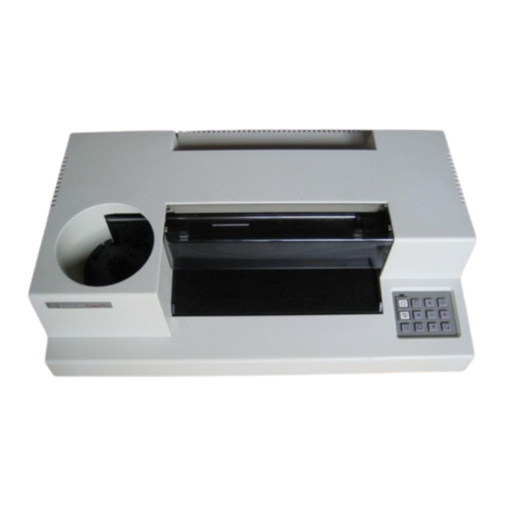
HP ColorPro HP7440A Manuals
Manuals and User Guides for HP ColorPro HP7440A. We have
1
HP ColorPro HP7440A manual available for free PDF download: Support Manual
HP ColorPro HP7440A Support Manual (135 pages)
Brand:
HP
| Category:
Plotter
| Size: 3 MB
Table of Contents
Table of Contents
4
HP 7440 Colorpro Plotter, Front View
9
HP 7440 Colorpro Plotter, Rear View
9
Product Information
10
Description
10
Options
10
Accessories
10
Specifications
10
Option 002
10
Accessories Supplied, Plotter
11
Accessories Supplied, Graphics
11
Specifications and Supplemental Characteristics
11
Serial Number Information
12
HP 7440 Serial Number Label
12
Test Equipment and Special Tools
13
Safety
13
Required Tools and Test Equipment
13
Site Planning and Requirements
14
Introduction
14
Electrical Specifications
14
Power Requirements
14
AC Power Module
14
Environmental Specifications
14
Physical Specifications
14
Cable Restrictions
14
Physical Dimensions
14
Installation and Configuration
16
Introduction
16
Unpacking and Inspection
16
Repacking, Storage, and Shipping
16
Installation
16
Line Voltage and Fusing
17
Available Ac Power Modules
17
Switch Settings
18
Front Panel Key Switches
18
Rear Panel Switches
18
CCITT V.24 Serial Interface)
18
Rear Panel Switches (HP-IB Parallel Interface) (Option 002)
18
Front Panel Key Switch Functions
19
HP 7440 Plotter Baud Rate Settings
19
Rear Panel Switch Functions
19
Interconnection
20
HP-IB Address Selection
20
HP-IB Parallel Interface (Option 002) Rear Panel Switch Functions
20
Self Test Procedures
21
Preliminary Test
21
Demonstration Plots
21
Demonstration Plot, Without GEC
21
Repeatability
22
Pen-To-Pen Repeatability
22
Loopback Test
22
System Verification
22
Demonstration Plot, GEC Installed
22
Hewlett-Packard Graphics Language
23
User Information
23
HP 7440 HP-GL Minimal Instruction Set
23
Demonstration Plot (with Valid Loopback Test)
23
System Verification Test Program
23
System Verification Plot
23
HP 7440 HP-GL Instruction Set Extension
25
Preventive Maintenance
26
Introduction
26
Effect on Product Reliability
26
Cleaning
26
User Cleaning Procedures
26
Service Personnel Cleaning Procedures
26
Mechanical Alignment
26
Electrical Alignment
26
Functional Description
28
Introduction
28
Simplified Description of Circuits
28
Functional Description of Circuits
28
Front Panel
28
Interfaces
28
Microprocessor
28
Support IC
28
Graphics Enhancement Cartridge (GEC)
29
Memory
29
Power Supply
29
Comparator
30
Grit Wheels, Pen Carriage, and Pen Carousel
30
Pen Carriage and Paper Motor Driver Ics, Circuits, and Motors
30
Encoders
30
Pen Lift Drive Circuits
30
Pen Solenoid
30
Rear Panel
30
Pen Carousel
30
Detailed Description of Main PCA Circuitry
30
(RS-232-C), Schematic Diagram
30
Microprocessor Circuitry
31
Comparator
31
Comparator Input and Output Signals
31
Diagram
31
HP 7440 Encoder PCA, Schematic Diagram
31
Support IC Circuitry
32
Tracking AID Converter Block Diagram
33
Read Only Memory Circuitry
34
Random Access Memory Circuitry
34
Motor Drive Circuitry
34
Motor Supply Sensor Circuitry
34
Capacitive Encoder Circuitry
34
Power Supply Circuitry
35
Encoder PCA Cover, Outer Side
35
Encoder PCA Cover, Inner Side
35
Encoder PCA, Outer Side
36
Encoder PCA, Inner Side
36
Encoder Sense Wheel and Return Plate
36
Graphics Enhancement Cartridge Circuitry
37
Functional and Detailed
37
Descriptions of I/0 Options
37
Functional Description of the RS-232-C/CCITT V.24 Interface (Option 001)
37
Enhancement Cartridge
37
Option 001
37
RS-232-C/CCITT V.24 Block Diagram
37
Detailed Description of the RS-232-C/CCITT V.24 Interface (Option 001)
38
Functional Description of the HP-IB Interface (Option 002)
38
Detailed Description of the HP-IB Interface (Option 002)
38
Remote Enable (Ren)
39
Removal and Replacement
42
Introduction
42
Safety Considerations
42
Required Tools/Equipment
42
Disassembly and Reassembly Procedures
42
Opening up the Plotter
42
Chassis Assembly Removal
42
Main PCA Removal
43
Opening up the Plotter
43
Chassis Assembly Removal
44
Main PCA Removal
44
Front Panel Assembly Removal
45
Pen Solenoid Assembly Removal
45
Pen Carriage Assembly Removal
45
Pen Lift Bar Removal
46
Pen Solenoid Assembly Removal
46
Pen Carriage Assembly Removal
46
Pen Lift Bar Removal
47
Pen Carriage Drive Motor/Encoder Assembly Removal
48
Pen Carriage Drive Motor/Encoder
48
Assembly Removal
48
Paper Drive Motor/Encoder Assembly Removal
49
Pinch Wheel Removal
50
Paper Drive Motor/Encoder Assembly Removal
50
Right Pinch Wheel Arm Removal
51
Pinch Wheel Removal
51
Left Pinch Wheel Arm
52
Removal
52
Grit Wheel Assembly Removal
52
Left Pinch Wheel Arm Removal
53
Clutch Assembly Removal
54
Grit Wheel Assembly Removal
54
Clutch Assembly Removal
55
Removal and Replacement Matrix
57
Disassembly and Reassembly Procedures
57
Matrix
57
Introduction
60
Troubleshooting and Diagnostics
60
Safety Considerations
60
Troubleshooting Strategy
60
Troubleshooting Procedures
60
Replaceable Parts
62
Introduction
62
Ordering Information
62
Exchange Pcas
62
Field Replaceable Parts Lists
62
Abbreviation List and Reference Designators
62
Code List of Manufacturers
62
Parts List, Top Case, Front Panel, and Base Assemblies
63
Top Case, Front Panel, and Base
64
Parts List, Chassis Assembly
65
Chassis Assembly, Illustrated Parts Breakdown
66
Parts List, Pen Carriage Assembly
67
Parts List, Exchange Assemblies
69
Reference Designators and Abbreviations
74
Reference Designations
74
Breakdown
74
Code List of Manufacturers
75
Reference
76
Introduction
76
Other Manuals
76
Glossary
76
Mnemonics
76
Other Technical Data
76
Product History
80
Introduction
80
History of Assemblies by Product Serial Prefix Number
80
History of Printed-Circuit Assemblies
80
PCA Date Codes
81
Diagrams
86
Introduction
86
Troubleshooting Chart
86
Engineering Diagrams
86
Functional Block Diagram
86
Electrical Diagrams
86
Troubleshooting Flowchart
99
Service Sheet
107
Functional Block Diagram
107
HP Model 7440
107
Cartridge
108
Table
108
HP 7440 Interconnecting Cable Identification Diagram
109
HP 7440 Main PCA, Option
114
HP 7440 Power Supply, Option
115
(RS-232-C), Schematic Diagram
119
HP 7440 Power Supply, Option
119
HP 7440 Main PCA, Option 002 (HP-IB), Schematic Diagram
124
HP 7440 Power Supply, Option
129
(HP-IB), Schematic Diagram
129
Cartridge PCA, Schematic Diagram
132
Advertisement
Advertisement
Related Products
HP HP700196
HP HP700198
HP HP-7035B
HP HP700/22
HP HP-75
HP HP-75D
HP HP700/92
HP HP700/94
HP HP-71
HP HPE StoreEasy 1660
HP Categories
Desktop
Laptop
Server
Monitor
Switch
More HP Manuals
Login
Sign In
OR
Sign in with Facebook
Sign in with Google
Upload manual
Upload from disk
Upload from URL