Sign In
Upload
Manuals
Brands
Hoval Manuals
Portable Generator
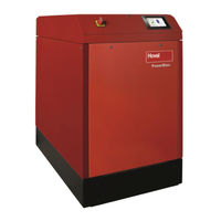
PowerBloc FG 20
Hoval PowerBloc FG 20 Portable Generator Manuals
Manuals and User Guides for Hoval PowerBloc FG 20 Portable Generator. We have
1
Hoval PowerBloc FG 20 Portable Generator manual available for free PDF download: Operating And Installation Manual
Hoval PowerBloc FG 20 Operating And Installation Manual (131 pages)
Brand:
Hoval
| Category:
Portable Generator
| Size: 6 MB
Table of Contents
Table of Contents
2
1 General Information
5
The Principle of Cogeneration
5
2 Basic Information
6
Copyright and Reservation of Rights
6
Warranty
6
Liability
7
Responsibilities of the Owner
7
Standards and Directives
8
Notes on the Representation of Symbols and Signal Words
10
Service Addresses
11
3 Safety
12
Basic Safety Instructions
12
Observance of the Operating Instructions
12
Qualification of the Personnel, Duty of Care of the Owner
12
Safety Markings on the Product
12
Safety Markings in this Manual
13
DANGER Marking
13
WARNING Marking
13
CAUTION Marking
15
IMPORTANT Marking
15
Waste Disposal
16
Intended Use of the Plant
16
General
16
Possible Misuse
17
Fire Hazard / Fire Fighting
17
Mechanical Hazards
17
Electrical Hazards
18
General Safety Instructions
18
Special Safety Instructions
21
Fuel Variants
21
Generator Protection
21
Coolant Tank with Safety Closure
21
Temperature Monitoring
21
Integrated Network and Plant Protection
22
CO Sensor (Optional)
22
Base Group with Frame
22
Driveline
22
Gas Engine
22
Generator
23
Lubricating Oil Supply
23
Gas Line
23
Heat Exchanger System
24
Power Factor Correction
25
4 Technical Documentation
26
Transport and Installation
28
Safety
28
Transport
29
Storage Conditions
29
Installation
30
Assembly and Installation
31
Installation and Connection Conditions
37
Installation Conditions of the Cogeneration Plant
40
Combustion Air
40
Extract Air
40
Condensate
41
Gas Connection
42
Electrical Integration
42
Hydraulic Integration into the Heating System
42
Dimensions and Weight
46
Floor and Base
46
Water Quality
46
Installation Diagram
47
Connection Conditions
48
Connection Diagram
49
Power Supply
51
5 Commissioning and Decommissioning
52
Commissioning
53
Safety
53
Assembly and Installation
54
Preparatory Work for Installation of the CHP Plant
54
Installing the CHP Plant
54
Connecting the CHP Plant
54
Connection Work
54
Start-Up
55
Preparing for Initial Commissioning
55
Carrying out Initial Commissioning
55
Decommissioning, Corrosion Protection and Disposal
56
Special Notes for Decommissioning
56
Final Decommissioning and Disposal
56
Corrosion Protection
57
Waste Disposal
57
6 ATROMATIC Operating Instructions
58
Introduction
58
Menu Structure
58
Main Screen
60
Chimney Sweep Function
62
Details - Menu Structure 1
63
History - Menu Structure 1.1
63
Power, Output, Network, Motor (Menu Structure 1.2.)
71
Temperatures (Menu Structure 1.3.)
72
Oil Change / Service Interval (Menu Structure 1.4.)
73
System Information / Language (Menu Structure 1.5.)
74
Code / Setup (Menu Structure 2.)
75
User Level 1
75
Power Curve (Menu Structure 2.1.)
76
Schedule (Menu Structure 2.2.)
77
Time / Date (Menu Structure 2.3.)
79
LAN (Menu Structure 2.4)
80
E-Mail (Menu Structure 2.5)
82
Additional Functions (Menu Structure 2.6.)
83
User Level 2
98
Oil Change (Menu Structure 2.6.9)
99
Service Interval (Menu Structure 2.6.10)
100
Allowed Power (Menu Structure 2.6.11)
101
Fresh Oil Pump (Menu Structure 2.6.12)
102
System Operator (Menu Structure 2.6.13)
103
Serial Number (Menu Structure 2.6.14)
104
Temperature Configuration (Menu Structure 2.6.15)
105
Manual Control (Menu Structure 2.6.16)
106
Other Parameters (Menu Structure 2.6.17)
107
Stop Mode / Error (Menu Structure 2.6.19)
112
Error Window
112
Error List (Menu Structure 2.6.20)
115
Warning (Menu Structure 2.6.21)
118
Standards
120
7 Service and Maintenance
121
Safety
121
Cleaning and Lubrication
122
Cleaning
122
Lubrication
122
Maintenance Intervals and Servicing Work
122
Maintenance Intervals
122
Repair Work
123
Connection Work
124
Electrical Installation
124
Connecting to the Electrical Grid
124
8 Remote Maintenance and Installation
125
Installing the Remote Maintenance Module
125
CHP Plant Software Configuration
127
Cascade Connection
128
Changing the Micro SD Card
129
Connection Diagram for the Remote Maintenance Module
130
Advertisement
Advertisement
Related Products
Hoval PowerBloc FG 12
Hoval PowerBloc FG 15
Hoval PowerBloc EG
Hoval PowerBloc FG
Hoval PowerBloc EG 12
Hoval PowerBloc EG 15
Hoval PowerBloc EG 20
Hoval HomeVent comfort FR 201
Hoval HomeVent comfort FR 251
Hoval Belaria fit 53
Hoval Categories
Boiler
Heat Pump
Controller
Industrial Equipment
Fan
More Hoval Manuals
Login
Sign In
OR
Sign in with Facebook
Sign in with Google
Upload manual
Upload from disk
Upload from URL