Sign In
Upload
Manuals
Brands
Hoval Manuals
Boiler
52-UltraGas 2 190
Hoval 52-UltraGas 2 190 Manuals
Manuals and User Guides for Hoval 52-UltraGas 2 190. We have
2
Hoval 52-UltraGas 2 190 manuals available for free PDF download: Installation Instructions Manual, Manual
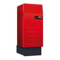
Hoval 52-UltraGas 2 190 Installation Instructions Manual (86 pages)
Floor-standing gas condensing boiler
Brand:
Hoval
| Category:
Boiler
| Size: 8 MB
Table of Contents
Table of Contents
2
Important Notices
4
System Manual
4
General Safety Instructions
4
Explanation of the Symbols
5
Warnings
5
Warning Symbols
5
Information
6
On Delivery
6
Transport
6
Guarantee
6
Regulations, Standards and Directives
7
Technical Information Description
8
Function Descriptions
9
Automatic Function Device BIC 970 (Brief Description)
9
Technical Data
10
Meaning of the Data on the Data Plate
10
Technical Data Ultragas ® 2 (125-1550)
11
Heating Water Side Flow Resistance
16
Dimensions
17
Ultragas ® 2 (125-1550) Dimensions
17
Overall Unit Dimensions
18
2.3.3 Space Requirement
19
2.3.3.1 Installation Variants with Reduced Height Requirements
20
Installation
21
Installation Location (Requirements on the Boiler Room)
21
Setting up Heat Generator
22
Requirements for Installation and Setting up
22
3.2.1.1 Suspension Option
22
Set-Up of Ultragas ® 2 (125,150)
23
Set-Up of Ultragas ® 2 (190-1550)
23
Installing Thermal Insulation
25
Mounting Cladding
26
Removing the Cladding for Maintenance and Service Work
32
Installation
32
Combustion Air Supply
34
Operation Dependent and Independent of Room Air
34
Room Air Dependent Installation (Construction B)
34
Installation Independent of Room Air (Construction C)
34
Flue Gas Connection, Flue Gas Line
35
Standard Values for Flue Gas Line Dimensions
36
Combustion Air/Flue Gas Ducting
38
Condensate Drain Line
39
Condensate Drain Engineering Guidelines
39
Installing Siphon and Condensate Drain Line
41
Installing Condensate Drain Line Siphon - Sewer System (Standard Design)
41
Installing Condensate Drain Line Siphon - Condensate Pump - Sewer System at Higher Level
42
Installing the Condensate Drain Line Siphon - Neutralisation Unit - Sewer System
43
Installing the Condensate Drain Line Siphon - Neutralisation Unit - Condensate Pump - Sewer System at Higher Level
44
Gas Connection
45
Venting the Gas Line
46
Checking the Gas Supply
46
Hydraulic Connection
47
Hydraulic Integration
48
4.5.1.1 Heat Generator Cascades
49
Water Quality in Heating Systems
50
Filling the Heating System
52
Electrical Connection
52
Safety Precaution for Installation in Line with EMC Requirements
54
Recommended Cable Cross-Sections and Maximum Permitted Cable Lengths
56
Commissioning
57
Prerequisites for Trial Operation
57
Commissioning Procedure
58
Switching the Heat Generator on
59
Checking the Parameter Settings
59
Checking the Gas Flow Pressure
59
Functional Check of Pressure Monitoring Device
59
Checking the Function of the Pressure Switch (Safety Check)
59
Changing the Heat Generator to a Different Type of Gas
60
Performing the Emission Measurement and Adjusting the Gas Quantity
60
Performing the Emission Measurement for Ultragas ® 2 (125-700)
61
Performing the Emission Measurement for Ultragas ® 2 (800-1550)
62
Monitoring Work before Handover to the Operator
64
Heat Generator Handed over to the Operator
64
Maintenance
65
Maintenance Work
66
Bleeding the Heating System
67
Replenishing Replacement Water
67
Information for Fire Inspector / Chimney Sweep Regarding Emission and Manual Operation Settings
68
Cleaning and Maintaining the Heat Generator
69
Servicing Motorised Combustion Air Damper (Option)
76
Renewing Fuse
78
Monitoring Work before Handover to the Operator
79
Decommissioning
80
Disconnecting the Heat Generator from the Mains
80
Appendix
81
BIC 970 Automatic Function Device Parameter List
81
Automatic Function Device Ultragas ® 2
81
Activate Screed Function
83
Advertisement
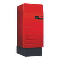
Hoval 52-UltraGas 2 190 Manual (78 pages)
Gas condensing boilers for natural gas in modulating operation
Brand:
Hoval
| Category:
Boiler
| Size: 22 MB
Table of Contents
Table of Contents
2
Important Notices
4
System Manual
4
General Safety Instructions
4
Explanation of the Symbols
5
Warnings
5
Warning Symbols
5
Information
6
On Delivery
6
Guarantee
6
Regulations, Standards and Directives
7
Technical Information Description
8
Function Descriptions
9
Automatic Function Device BIC 970 (Brief Description)
9
Technical Data
10
Meaning of the Data on the Data Plate
10
Ultragas ® 2 (125-1550) Technical Data
11
Heating Water Side Flow Resistance
16
Dimensions
17
Ultragas 2 (125-1550) Dimensions
17
Overall Unit Dimensions
18
2.3.3 Space Requirement
19
2.3.3.1 Installation Variants with Reduced Height Requirements
20
Installation
21
Installation Location (Requirements on the Boiler Room)
21
Setting up Heat Generator
21
Requirements for Installation and Setting up
21
3.2.1.1 Suspension Option
21
Set-Up of Ultragas ® 2 (125,150)
22
Set-Up of Ultragas ® 2 (190-1550)
22
Installing Thermal Insulation
24
Mounting Cladding
25
Removing the Cladding for Maintenance and Service Work
31
Installation
33
Combustion Air Supply
33
Room Air Dependent Installation
33
Room Air Independent Installation
33
Flue Gas Connection, Flue Gas Line
34
Standard Values for Flue Gas Line Dimensions
35
Combustion Air/Flue Gas Ducting
36
Condensate Drain
37
Condensate Drain Engineering Guidelines
37
Installing Siphon and Condensate Drain
39
Installing Condensate Drain Siphon - Sewer System (Standard Design)
39
Installing Condensate Drain Siphon - Condensate Pump - Sewer System at Higher Level
39
Installing the Condensate Drain Siphon - Neutralisation Unit - Sewer System
40
Installing the Condensate Drain Siphon - Neutralisation Unit - Condensate Pump - Sewer System at Higher Level
40
Gas Connection
41
Venting the Gas Pipe
42
Hydraulic Connection
43
Hydraulic Integration
44
4.5.1.1 Heat Generator Cascades
45
Water Quality in Heating Systems
46
Filling the Heating System
48
Electrical Connection
49
Safety Precaution for Installation in Line with EMC Requirements
50
Recommended Cable Cross-Sections and Maximum Permitted Cable Lengths
52
Commissioning
53
Prerequisites for Trial Operation
53
Commissioning Procedure
54
Checking the Parameter Settings
54
Switching the Heat Generator on
55
Checking the Gas Flow Pressure
55
Functional Check of Pressure Monitoring Device
55
Checking the Function of the Pressure Switch (Safety Check)
55
Setting the Gas Quantity, Measuring the O
56
Flue Gas Measurement Ultragas ® 2 (125-700)
56
Flue Gas Measurement Ultragas ® 2 (800-1550)
57
Changing to a Different Type of Gas
58
Monitoring Work before Handover to the Operator
58
Heat Generator Handed over to the Operator
58
Maintenance
59
Maintenance Work
59
Bleeding the Heating System
60
Replenishing Replacement Water
60
Information for Fire Inspector / Chimney Sweep Regarding Emission and Manual Operation Settings
61
Cleaning and Maintaining the Heat Generator
62
Setting the Gas Quantity, Measuring the O (CO ) and Nox/Co Content in the Flue Gas
68
Servicing Motorised Combustion Air Damper (Option)
69
Renewing Fuse
72
Monitoring Work before Handover to the Operator
72
Appendix
73
BIC 970 Automatic Function Device Parameter List
73
Automatic Function Device Ultragas ® 2
73
Activate Screed Function
75
Advertisement
Related Products
Hoval 52-UltraGas 2 125
Hoval 52-UltraGas 2 150
Hoval 52-UltraGas 2 230
Hoval 52-UltraGas 2 300
Hoval 52-UltraGas 2 350
Hoval 52-UltraGas 2 400
Hoval 52-UltraGas 2 500
Hoval 52-UltraGas 2 530
Hoval 52-UltraGas 2 620
Hoval 52-UltraGas 2 700
Hoval Categories
Boiler
Heat Pump
Controller
Fan
Industrial Equipment
More Hoval Manuals
Login
Sign In
OR
Sign in with Facebook
Sign in with Google
Upload manual
Upload from disk
Upload from URL