Sign In
Upload
Manuals
Brands
HORNER Manuals
Controller
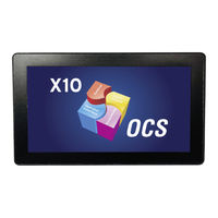
HE-X10R
HORNER HE-X10R Manuals
Manuals and User Guides for HORNER HE-X10R. We have
1
HORNER HE-X10R manual available for free PDF download: User Manual
HORNER HE-X10R User Manual (179 pages)
Brand:
HORNER
| Category:
Controller
| Size: 6 MB
Table of Contents
2: Method
2
Limited Warranty and Limitation of Liability
2
Table of Contents
4
Safety and Compliance
8
Chapter 1: Safety and Compliance
9
Warnings
9
FCC Compliance
10
Safety Precautions
10
Chapter 2: Intro to the X10
12
Visual Overview
12
Where to Find more Information for the X10 OCS
12
Four Main Types of Information Are Covered in this Manual
13
Connectivity to the X10
13
Features of X10 Micro OCS
14
Mechanical Installation
15
Chapter 3: Mechanical Installation
16
Mounting Overview
16
Mounting Procedures (Installed in a Panel Door)
16
Mounting Clip Locations
17
1: X10 OCS Mounting Orientation
17
Dimensions
18
Installation Procedure
19
Factors Affecting Panel Layout Design and Clearances
19
1: Clearance/Adequate Space
20
2: Grounding
20
3: Temperature/Ventilation
20
4: Noise
20
5: Shock and Vibration
20
6: Panel Layout Design and Clearance Checklist
21
Electrical Installation
22
Chapter 4: Electrical Installation
23
Ground Specifications
23
How to Test for Good Ground
23
Primary Power Port
24
1: DC Input/Frame
24
2: Power up
24
System Settings and Adjustments
25
Chapter 5: System Settings and Adjustments
26
System Menu - Overview
26
1: System Menu Map
28
Navigation and Editing
29
Set Networks
30
Set Network Baud Rate
31
View Status
32
View Diags
33
View Protocols
34
Set Fkeys
35
Set Serial Ports
36
Set Time/Date
36
Calibrate Analog
37
Set Beeper
38
Set Screen
38
Removable Media
39
Fail - Safe System
40
Enable Autorun
41
Enable Autoload
42
Clone Unit
43
Make Clone
43
1: Load Clone
43
Webmi License Details
44
Touch Screen Calibration
45
Register Mapping
46
Chapter 6: Registers
47
Register Definitions
47
S Registers
47
SR Registers
48
I/O Register Map for X10 OCS
49
X10 Resource Limits
49
PWM Function Registers Map
50
HSC Functions Registers Map
50
Cscape Configuration
51
Chapter 7: Cscape Configuration
52
Overview
52
Cscape Status Bar
52
Establishing Communications
53
Communicating Via MJ1 Serial Port
56
Communicating Via on Board Ethernet Port
58
1: Configure the Ethernet Settings Via a PC
58
2: Configure Ethernet Via Cscape
60
Digital Input Configuration
61
Digital Output Configuration
64
Analog Input Configuration
67
Scaling Analog Inputs & Examples
71
Analog Output Configuration
72
Chapter 8: General I/O Configuration
77
Built-In Digital and Analog I/O Overview
77
1: Model and I/O Overview
77
Solid-State Digital Outputs
78
1: Model a & Model R Digital Output Wiring
79
2: Relay Outputs
80
J1 Wiring: Model R - Relay/Digital out
81
1: Model R: Sinking and Sourcing Outputs
82
Digital / HSC Input Configuration
83
Positive Logic Vs. Negative Logic
83
1: J2 Wiring: Models R & a - Digital Input
83
I/O Status and Calibration
84
1: I/O Status
84
2: I/O Calibration
84
3: to Calibrate 0-20Ma, 4-20Ma, or RTD PT100 Analog Inputs
85
4: to Calibrate 4-20Ma Analog Outputs
85
RTD Wiring on J3 Connector
86
X 4-20Ma Input/4-20Ma Output
87
High Speed I/O (HSC & PWM)
88
Chapter 9: High Speed I/O
89
Overview
89
High Speed Counter (HSC) Functions
89
1: Frequency
90
2: Totalize
91
3: Pulse
92
4: Period Measurement
92
5: Quadrature
93
6: Sync Pulse Mode Table
95
High Speed Counter
96
1: HSC Register Map for Micro OCS
96
Pulse Width Modulation (PWM) Functions
97
1: PWM Output Waveform
98
2: PWM Functions Register Map
98
3: PWM Examples
99
HSC Pulse Output
99
Serial Communications
100
Chapter 10: Serial Communications
101
Port Descriptions
101
Wiring-MJ1/MJ2 Serial Ports
101
RS-485 Termination and Biasing
101
Cscape Programming Via Serial Port
102
Ladder-Controlled Serial Communication
102
Configuration Via Mini-B USB
102
Chapter 11: CAN Communications
104
Overview
104
CAN Port Wiring
104
Cscape Programming Via CAN
105
Ladder-Controlled CAN Communication
105
CAN for I/O Expansion (Network I/O)
105
CAN and Termination and Bias
105
Ethernet Communication
106
Chapter 12: Ethernet Communications
107
Ethernet Module Protocols
107
Ethernet System Requirements
107
Ethernet Module Specifications
107
Ethernet Module Configuration
107
Ethernet Configuration - IP Parameters
111
Ethernet Module Protocol Configuration
111
Chapter 13: Protocol Configuration
113
Overview
113
Protocol Device Driver Selection
114
Network Configuration
115
Device List and Device Configuration
116
1: Device List
116
2: Device Configuration
117
Scan List
118
1: Menu
119
2: Buttons
119
3: Display Control
119
4: Data Mapping Configuration (Scan List Entry)
120
User Interface
123
Chapter 14: User Interface
124
Screen Specifications
124
Displaying and Entering Data
124
Numeric Keypad
125
Screen Navigation
126
Ladder Based Screen Navigation
127
Touch (Slip) Sensitivity
127
Alarms
128
1: Alarm Viewer
128
Removable Media
129
Screen Saver
130
Screen Brightness
130
Chapter 15: Removable Media
132
Microsd Cards
132
1: Microsd File System
133
Using the Removable Media Manager
133
Log Data
134
View and Capture Screens
134
Removable Media Object
134
Function Blocks in Cscape
135
1: Program Features
135
2: Graphic/Screen Editor
135
3: Additional Configuration
136
Filenames
136
System Registers Used with RM
136
Clone Unit
138
Chapter 16: Clone Unit
139
Make Clone
139
Load Clone
142
Fail-Safe System
144
Chapter 17: Fail-Safe System for the XL and X Series
145
For the XL & X Series
145
Fail-Safe System Overview
145
Settings
146
Backup/Restore Data
146
1: Backup OCS Data
147
2: Restore OCS Data
147
Clear Backup Data
147
Autoload
150
Autorun
152
Chapter 18: Modbus Communications
154
Modbus Slave Overview
154
Modbus Master Overview
155
Modbus Addressing Table
156
Firmware Update
157
Chapter 19: Firmware Updates
158
Check for Current Firmware Revision
158
Firmware Update Details
159
Download Firmware
159
Firmware Update Steps
160
Firmware Update Via Microsd Card
160
1: Method
160
Backup Battery
163
Chapter 20: Battery
164
Low or Missing Battery
164
1: Lost Program
165
Steps to Replace the Battery
165
Chapter 21: Troubleshooting
167
Connecting to the OCS
167
1: Serial Port - MJ1 Programming
168
2: USB Port - Mini Btype C Programming
168
3: ETN Port Programming
168
Local Controller and Local I/O
169
1: Local I/O Troubleshooting Checklist
169
Cscan Network
169
1: Cscan Network Troubleshooting Checklist
170
USB Interfaces
170
Basic Troubleshooting
171
Technical Support Contacts
171
X10 Change Log
172
Chapter 22: Index
173
Advertisement
Advertisement
Related Products
HORNER HE-X10A
HORNER HE-XE100
HORNER HE-XE1E4
HORNER HE-XE1E5
HORNER HE-XT1E4
HORNER HEXE220C100
HORNER HEXT240C114
HORNER HEXT240C115
HORNER HEXT240C116
HORNER HEXT241C100
HORNER Categories
Controller
Touchscreen
Control Unit
Control Systems
Control Panel
More HORNER Manuals
Login
Sign In
OR
Sign in with Facebook
Sign in with Google
Upload manual
Upload from disk
Upload from URL