Sign In
Upload
Manuals
Brands
HMS Manuals
Control Unit
IXXAT Safe T100
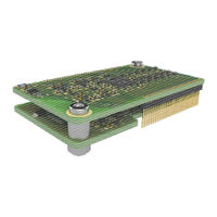
User Manuals: HMS IXXAT Safe T100 Safety Module
Manuals and User Guides for HMS IXXAT Safe T100 Safety Module. We have
2
HMS IXXAT Safe T100 Safety Module manuals available for free PDF download: Safety Manual–Original Instructions, Hardware Manual
HMS IXXAT Safe T100 Safety Manual–Original Instructions (174 pages)
Brand:
HMS
| Category:
Control Unit
| Size: 2 MB
Table of Contents
Table of Contents
3
1 Preface
9
Important User Information
9
T100 Safety Precautions
10
Liability
10
Intellectual Property Rights
11
Trademark Acknowledgements
11
About this Document
11
Related and Additional Documents
12
Document History
13
Conventions & Terminology
14
Abbreviations
16
Restrictions
18
Handling
18
Area of Application
18
Validity of this Safety Manual
18
Service and Maintenance
19
End of Life
19
Disclaimer
19
Support
19
Returning Hardware
20
CE Pre-Testing
21
Information on EMC
21
Product Change Requests
21
2 General Description
22
Background
22
IXXAT Safe T100
22
The Black Channel Approach
24
3 T100 Operation
25
Overview
25
Safety Functions
25
Pinning
26
Power Supply
28
Voltage Levels and Power Consumption, 24V
28
Reverse Battery Protection, 24V
30
EMC Protection, 24V
31
Clamp Diode
31
HF Filter
31
Voltage Levels and Power Consumption, EXT_3V3
32
Ground Concept
33
Galvanic Isolation
34
Integrated I/O Protection Circuits
34
Safe Operation
35
Safe Digital Inputs
35
DI-C Contact Inputs
36
DI-S Semiconductor Input
38
Input Wiring Examples
38
Digital Input Diagnosis and Safe State
39
Safe Application DI Reaction Time
39
DI Diagnostic Test Interval
40
Reliability Block Diagram
40
Test Outputs
42
Safe Digital Outputs
44
Digital Output Diagnosis and DO Diagnostic Test Interval
45
Loss of Ground at DO
46
Safe Application DO Reaction Time
46
Output Wiring Examples
48
Reliability Block Diagram
49
Safe State and Reaction Times
50
Hardware Interfaces to Non-Safe Components
55
T100 Hardware Reset Conditions
56
Powerup Reset
56
Restart Reset
57
Wiring Example
58
T100 Firmware Update
59
T100 Module Identification
60
Operating States
61
T100/PS Specific States
61
T100/CS Specific States
63
4 In-Design
65
Mechanical Specification
65
T100 Dimensions
65
Connection to Host Board
65
Mounting Recommendations
66
Mechanical Mounting Set Recommendations
66
Clearances
67
Allowed Mounting Positions
68
Labeling of Safety Signals
68
Environmental Considerations
69
Layout Rules
69
Temperature
70
Temperature Verification Inside Cdev
70
Shock / Vibration
71
Humidity and Pollution Level
72
Intrusion Protection
72
Maximum Operation Altitude
72
Emc
73
T100 Radiated Emission
75
5 Configuration and Programming
76
Configuration of Safety Inputs
77
Enable
77
Channel Type
77
Debounce Filter
78
Channel Mode
80
Consistency Filter
81
Reset of Input Errors
82
Non-Safe Read Access
82
Configuration of Test Outputs
83
Configuration of Safety Outputs
85
Channel Mode
85
Enable
86
Output Test
86
Reset of Output Errors
88
Pre-Tested Configurations
89
Profisafe Configurations
89
Dual-Channel DI-C
89
Dual-Channel DI-S
90
Mixed DI-C Dual/Single Channel
91
CIP Safety Configurations
92
Dual-Channel DI-C
92
Dual-Channel DI-S
93
Mixed DI-C Dual/Single Channel
94
6 Safety Fieldbus Communication
95
General
95
Profisafe
96
Profisafe Configuration Sequence
96
F-Parameter Setup
97
F-Address
98
Iparameter CRC
98
Watchdog Time
98
Iparameter Setup
99
GSD File
102
Iparameter CRC Calculation Tool
104
T100/PS Status Information
104
F-Data Exchange
104
Input Process Image
105
Output Process Image
107
Error Handling
109
T100/PS Temperature Sensor Data Access
110
Device Replacement
110
Profisafe Certification
111
CIP Safety
112
CIP Object Model
112
Class Attributes
112
Instance Attributes
112
Safety Supervisor Object (0X39)
112
Class Attributes
115
Safety Validator Object (0X3A)
115
Services
115
Instance Attributes
116
Services
118
Class Attributes
119
Safety Discrete Output Point Object (SDOP) (0X3B)119
119
Instance Attributes
119
Services
120
Safety Discrete Input Point Object (SDIP) (0X3D)
120
Class Attributes
120
Instance Attributes
120
Safety Discrete Input Group Object (SDIG) (0X3E)
121
Class Attributes
121
Instance Attributes
121
Services
121
Safety Dual Channel Output Object (SDCO) (0X3F)122
122
Class Attributes
122
Instance Attributes
122
Services
122
Diagnostic Object (0X64)
123
Class Attributes
123
Instance Attributes
123
Services
123
Failure Code Object (0X65)
124
Class Attributes
124
Instance Attributes
124
Services
125
CIP Safety Configuration Sequence
126
Configuration Steps and States
126
Reset Services
128
Configuration Data String
129
SCID Calculation
131
Safety Data Exchange
132
Safe Input Data
133
Safe Output Data
135
Error Handling
136
Safe Input and Output Channel Error Handling
136
Event-Log
137
Fail-Safe Errors
138
Configuration Data Storage Errors
138
Status and Diagnostic Information
139
Parameters for Connection Establishment
140
LED Signaling
141
Device Replacement
141
Requirements for the End User Manual
142
Requirements for the End Device (Cdev)
144
CIP Safety Certification
145
7 Re-Certification Steps
146
General Cdev Integration and Re-Certification Steps
146
8 Characteristics
148
9 Compliance
150
IEC 61508 and en ISO 13849
150
Fieldbus Compliance
151
Profisafe
151
CIP Safety
151
Rohs
151
Emc
151
Appendix
152
A Safety Integration Rules
153
B Safety Application Rules
157
C Applicable Standards
164
DCIP Safety Event and Error Codes
166
E Declaration of Incorporation
174
Advertisement
HMS IXXAT Safe T100 Hardware Manual (48 pages)
Brand:
HMS
| Category:
Microcontrollers
| Size: 3 MB
Table of Contents
Table of Contents
4
Document History
6
Referenced Documents
6
Abbreviations
7
1 Overview
8
Anybus Compactcom Objects
11
Functional Safety Object
12
2 Power Supply Connection
13
3 Address Switches
14
Profisafe F-Address
14
CIP Safety IP Address
15
Fsoe Slave Address
18
4 Enable the Safety Module
19
Communication Cycle Time
20
5 Non-Safe Process Data Handling
21
Profinet
22
Ethernet/Ip
22
Ethercat
22
Non-Safe Input Data
23
Non-Safe Output Data
25
6 Network Configuration
27
Profinet (Gsdml)
27
Ethernet/Ip
27
Electronic Data Sheet (EDS)
27
Configuration Data String
27
PLC Configuration in Rslogix Designer (Studio 5000)
28
Device Identity and Connections
28
SCID (Safety Configuration Identifier)
29
Safety Network Number / TUNID
30
Ethercat (ESI)
30
7 Fault Reset Button
31
Manual Fault Reset
31
Automatic Fault Reset
31
8 Reset Button
32
Copyright HMS TC Ravensburg Gmbh Development Kit Manual
32
9 LED Indicators
33
Profisafe
33
CIP Safety
34
Fsoe
34
10 Safety I/O Connectors
35
11 Other Components
36
Jumper
36
Switch S1
36
Pin Header JP18
36
JTAG Connector
36
RS232 Connector JP7
36
12 Web Page
37
13 Wiring Diagram
38
14 Product Support and Conformity
44
Support
44
Returning Hardware
44
Information on EMC
44
EC Declaration of Conformity
45
Appendix A - ADI Configuration
46
Adi 1
46
Adi 2
47
Appendix B - Firmware Upgrade
48
Development Kit Board
48
Anybus Compactcom
48
T100
48
Advertisement
Related Products
HMS ATLAS TYTAN 10
HMS ATLAS TYTAN 9
HMS TYTAN 15
HMS TYTAN 5
HMS TYTAN PRO
HMS ATLAS TYTAN 7
HMS TX10
HMS TX PRO
HMS ATLAS TYTAN 11
HMS TRYTON
HMS Categories
Fitness Equipment
Gateway
Exercise Bike
Treadmill
Network Hardware
More HMS Manuals
Login
Sign In
OR
Sign in with Facebook
Sign in with Google
Upload manual
Upload from disk
Upload from URL