Sign In
Upload
Manuals
Brands
Hitachi Manuals
Heat Pump
SET FREE Series
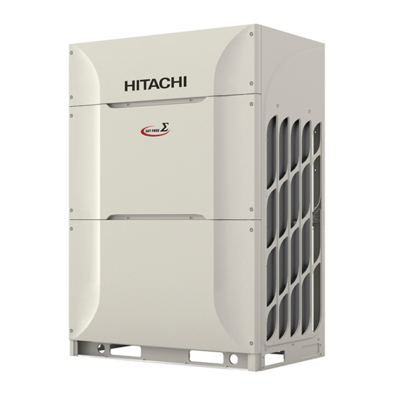
Hitachi SET FREE Series Manuals
Manuals and User Guides for Hitachi SET FREE Series. We have
4
Hitachi SET FREE Series manuals available for free PDF download: Service Manual, Instruction Manual
Hitachi SET FREE Series Instruction Manual (612 pages)
Brand:
Hitachi
| Category:
Heat Pump
| Size: 83 MB
Table of Contents
Table of Contents
9
General Information
11
Safety
11
Combination of Outdoor Units
12
Important Notice
16
Transport, Lifting and Handling of the Units
17
Name of Parts
20
Unit Installation
27
Piping Work and Refrigerant Charge
30
Drain Piping
56
Electric Wiring
57
Commissioning
65
Main Safety Devices
68
Información GENERAL
71
Seguridad
71
Combinación de UNIDADES EXTERIORES
72
Aviso Importante
76
TRANSPORTE, IZADO y Manipulación de las UNIDADES
77
Nombre de Los Componentes
80
Instalación de la UNIDAD
87
Instalación de las Tuberías y CARGA de REFRIGERANTE
90
Tubería de DESAGÜE
116
Cableado Eléctrico
117
Puesta en Marcha
125
Principales Dispositivos de Seguridad
128
Allgemeine Informationen
131
Sicherheit
131
Kombination von Aussengeräten
132
Wichtiger Hinweis
136
Transport, Anheben und Bedienung der Geräte
137
Teilebezeichnungen
140
Geräteinstallation
147
Rohrleitungen und Kältemittelmenge
150
Abflussleitungen
176
Kabelanschluss
177
Inbetriebnahme
185
Grundlegende Sicherheitsvorrichtungen
188
Informations Générales
191
Sécurité
191
Combinaison de Groupes Extérieurs
192
Remarque Importante
196
Transport, Levage et Manipulation des Unités
197
NOMENCLATURE des Pièces
200
Installation des Unités
207
INSTALLATION des TUYAUTERIES et CHARGE de FLUIDE Frigorigène
210
Tuyauterie D'évacuation
236
10 Câblage ÉLECTRIQUE
237
Mise en Service
245
Principaux Dispositifs de Sécurité
248
Informazioni Generali
251
Sicurezza
251
COMBINAZIONE DI Unità ESTERNE
252
Nota Importante
256
TRASPORTO, SOLLEVAMENTO E MOVIMENTAZIONE DELLE Unità
257
Nome Dei Componenti
260
INSTALLAZIONE Dell'unità
267
Posa Dei Tubi E Carica DI Refrigerante
270
Linea DI Drenaggio
296
Collegamenti Elettrici
297
Messa in Esercizio
305
Principali Dispositivi DI Sicurezza
308
Informação GERAL
311
Segurança
311
Combinação de UNIDADES EXTERIORES
312
Nota Importante
316
TRANSPORTE, Suspensão E MANUSEAMENTO das UNIDADES
317
NOME das Peças
320
Instalação da UNIDADE
327
Tubagem de Refrigerante E Carga de Refrigerante
330
Tubagem de Descarga
356
Ligações ELÉTRICAS
357
Colocação EM FUNCIONAMENTO
365
DISPOSITIVOS de Segurança PRINCIPAIS
368
Generel Information
371
Sikkerhed
371
KOMBINATION AF Udendørsenheder
372
Vigtig Information
376
TRANSPORT, Løft OG Håndtering AF ENHEDERNE
377
NAVN På DELE
380
Montering Af Enheden
387
Rørarbejde OG Påfyldning AF Kølemiddel
390
Afløbsrør
416
Elektriske Ledninger
417
Idriftsættelse
425
Primære SIKKERHEDSANORDNINGER
428
Algemene Informatie
431
Veiligheid
431
Combinatie Van Buitenunits
432
Belangrijke MEDEDELING
436
UNITS TRANSPORTEREN, Hijsen en VERPLAATSEN
437
Naam Van Onderdelen
440
Unit Installeren
447
Leidingen en Koudemiddelleiding Leggen
450
Afvoerleiding
476
Elektrische Bedrading
477
Inbedrijfsstelling
485
Belangrijkste VEILIGHEIDSVOORZIENINGEN
488
Allmän Information
491
Säkerhet
491
Kombination Av Utomhusenheter
492
Viktigt Meddelande
496
Transport, Lyft Och Hantering Av Enheterna
497
Delarnas Namn
500
Installation
507
RÖRDRAGNINGSARBETE OCH Påfyllning AV KYLMEDIUM
510
Dräneringsrör
536
Elektrisk Anslutning
537
Driftsättning
545
Huvudsakliga Säkerhetsanordningar
548
Γενικεσ Πληροφοριεσ
551
Ασφαλεια
551
Συνδυασμοσ Εξωτερικων Μοναδων
552
Σημαντικη Παρατηρηση
556
Μεταφορα, Ανυψωση Και Χειρισμοσ Των Μοναδων
557
Ονοματα Εξαρτηματων
560
Εγκατασταση Μοναδασ
567
Εργασιεσ Σωληνωσησ Και Πληρωσησ Ψυκτικου Μεσου
570
Σωληνωση Αποχετευσησ
596
Ηλεκτρικη Καλωδιωση
597
Εναρξη Λειτουργιασ
605
Συσκευεσ Ασφαλειασ
608
Advertisement
Hitachi SET FREE Series Service Manual (432 pages)
Heat pump / Heat recovery system
Brand:
Hitachi
| Category:
Heat Pump
| Size: 42 MB
Table of Contents
Table of Contents
4
General Information
14
Introduction
14
Applied Symbols
15
Norms And Regulations
16
Product Guide
17
Classification Of Outdoor Unit
17
Classification Of The Ch-Box
17
Icons Description
18
Product Line-Up: Outdoor Units
19
Product Line-Up: Ch-Box
20
Base Units
21
Build Up Capacity Combination
21
Unit Combinations
22
Accessory Code List
25
Product Line-Up: Indoor Units
26
Product Line-Up: Hydro Free
31
Low Temperature
31
High Temperature
31
Product Line-Up: Kpi Energy Recovery Units
32
Product Line-Up: DX-Interface
33
Electrical Wiring
34
Outdoor Unit
35
General Information
35
Outdoor Unit
35
General Information
35
Electrical Wiring Diagrams Of The Outdoor Units
37
Electrical Wiring Diagrams CH-Box
38
Box
40
General Information
40
General Information
40
Control System
47
Cycle Control for Heat Pump
47
Compressor Operation Control
47
Compressor Rotation Control
47
Cycle Control for Heat Recovery
48
Compressor Frequency Control
56
Compressor Capacity Control
60
Heat Exchanger Mode Control (2 Pipe System)
60
Heat Exchanger Mode Control (3 Pipe System)
62
Outline of the Control System
67
Standard Operation Sequence
68
Cooling Operation
68
Dry Operation
70
Antifreeze Protection Control During the Cooling or Dry Operation
72
Heating Operation
73
Defrost Operation
75
Excessive High Discharge Air Temperature Prevention Control (Depending on the Indoor Unit Model)
76
Protection Control
77
Control of the Outdoor Unit
77
Operating Conditions
83
Oil Return Control
86
Outdoor Unit
87
Control of CH-Box
88
Control and Safety Devices
90
Compressor Protection
90
Box
90
Optional Functions
93
Optional Functions Available In The Outdoor Units
93
Optional Functions Field Settings
95
Installation Settings
96
External Input And Output Setting
98
Menu Mode Accessing (By 7-Segment Display)
98
Check Mode
99
External Input And Output Setting
99
Function Setting
99
External Input And Output Setting (By 7-Segment Display)
100
Available Control Functions
100
Setting Of External Input And Output
101
External Input Function Setting
102
Setting Example
103
Operating Example
104
External Output Function Setting
107
Function Setting (By 7-Segment Display)
110
Sequence Of The Function Setting
110
Function Setting
114
Record Settings
119
Circulator Function At Heating Thermo-OFF (FA)
121
Night-Shift (Low Noise)(Ni)
122
Cancellation Of The Outdoor Ambient Temperature Limit (Gs)
123
Defrost For Cold Area (Jo)
124
Slo Defrost Setting (Bj)
125
Priority Capacity Mode Setting (Nu)
125
Low Noise Setting (Db)
126
Demand Function Setting(De)
127
Demand Control
127
Wave Function Setting (Ue)
128
Cold Draft Protection (Fb)
129
Adjustment Of Fan Rotation (Fo)
129
Alternate Defrosting Function (L)
130
Outdoor Fan Motor Intermittent Operation Setting (F4)
130
Frostwash (F1)
131
Minimum Evaporating Temperature Setting For Cooling (Hc)
138
Cool/Heat Auto Changeover Enable/Disable Setting (F8)
138
Power Saving Function From Wired Controller
146
Power Savings Mode Settings
146
Intermittent Control Function
150
Power Consumption Display Function
152
Preliminary Checks
155
Before the Test Run
156
Test Run Using the PC-ARFG2-E Remote Control
157
Test Run from the Outdoor Unit
160
Checking at Test Run
162
Reset For Accumulated Operation Time Of Compressor 1-2 (Cu1-Cu2)
164
Setting Of Forced Open Valve Mode
165
Heat Recovery
166
Refrigerant Cycle Checklist
167
Test Run Check List
170
Outdoor Unit PCB (PCB1)
174
Arrangement of Connectors and Check Points
174
Checking Procedures for Outdoor Unit PCB1
175
Inverter (INV1, INV2)
176
Inverter Specifications
176
High Voltage Discharge Work for Replacing Parts
178
Checking Method of Inverter PCB (INV)
179
Protection Function
186
Overload Protection Control
188
Inverter Failure Diagnosis Mode
189
Scroll Compressor
190
Reliable Mechanism for Low Vibration and Low Sound
190
Compression Principles
190
Structure
191
Compressor Type
191
Checking of Compressor Motor
192
Check List on Compressor
192
Additional Information for "Check List on Compressor
193
Fan Motor
194
Thermistors
195
Thermistor Positions for RAS-(8-12)FSXNS2E and RAS-(5/6)FSXNP2E
195
Thermistor Positions for RAS-(14-18)FSXNS2E and RAS-(8-14)FSXNP2E
196
Thermistor Positions for RAS-(20-24)FSXNS2E and RAS-(16/18)FSXNP2E
197
Thermistor (Td) for Discharge Gas Temperature
198
Thermistor for the Outdoor Ambient Temperature
198
Thermistor for the Evaporating Temperature of the Outdoor Unit in the Heating Operation (for Defrosting)
199
Thermistor for Super Cooling Bypass and Main Line Temperature of Outdoor Unit
199
Electronic Expansion Valve (MV1, MV2, MVB)
199
Specifications for MV1 and MV2
200
Specifications for MVB
201
Pressure Sensor (Pd)
202
High Pressure Control
202
Low Pressure Control
203
High Pressure Protection Device (PSH)
204
Electrical Coil Parts
205
Noise Filter (NF1, NF2)
205
Reactor (DCL1 and DCL2)
207
Box PCB (PCB1)
208
Check Points PCB1 of Single Type CH-Box
208
Check Points PCB1-4 of Multi Type CH-Box
208
Specifications for MVD1 and MVS1
209
Checking Method
209
Removing the Front Covers
213
Removing Service
213
Removing Bottom
214
Removing Front Right Cover
214
Removing the Electrical Box Covers
215
Removing the Electrical Box Cover
215
Removing the Electrical Box
215
Removing the Electrical Box
216
Reassembling the Electrical Box
218
Removing the Fan Grill
219
Removing the Fan of the Outdoor
220
Removing the Compressor
222
All Models
229
Replacing the Refrigerant Oil
232
No Clogging in Return Oil Circuit
232
Clogging in Return Oil Circuit and Replacing Return Oil Circuit
233
Removing the Coils
236
Coil Position
236
Removing the Expansion Valve Coil (MV1, MV2, MVB)
237
Removing the Solenoid Valve Coil (SVA, SVG)
238
Removing the Reversing Valve Coil (RVR1, RVR2)
239
Removing the Valves
239
Removing the Expansion Valve (MV1, MV2, MVB)
239
Removing the Solenoid Valve (SVA, SVX2, SVG)
240
Removing the Reversing Valve
241
Removing the Stop Valve
243
Removing the PSH, High and Low Pressure Sensors and Thermistors
244
High Pressure Switch, High/Low Pressure Sensor Position and Thermistors
244
Removing the High Pressure Switch (PSH1, PSH2)
246
Removing the High Pressure (Pd) and Low Pressure (Ps) Sensor
246
Removing the Pipe Thermistor
247
Removing the Ambient Temperature Thermistor
248
Removing Other Electrical Components
249
Removing the PCB1 and Electrical Components
249
Removing the Inverter PCB
257
Location of the Fuses on Electrical Components
258
Removing Components for CH-Box
259
Removing the Front Service Cover for Electrical Box and Electronic Expansion Valve
259
Removing the Electrical Components
260
Removing Electronic Expansion Valve Coil
264
Initial Troubleshooting
269
Checking The Electrical Wires And The Power Source
269
Checking By 7-Segment Display
270
Checking Of The Alarm Code History
271
Emergency Mode Operation from the Remote Control
277
Operating Condition
278
Emergency Mode Operation from the Outdoor Unit PCB1 for Compressor Failure
278
For Combination of Outdoor Units
278
Alarm Code
279
For Outdoor Units Without Combination
280
Failure of the Power Supply to Indoor Units and the Remote Control Switch
282
Abnormal Transmission Between Remote Control Switch And Indoor Unit
283
Abnormal Operation Of The Devices
284
Procedure For Troubleshooting
295
Alarm Codes Of Wired Controller
295
Alarm Code Ch-Box
300
Troubleshooting By Alarm Code
301
Troubleshooting By Using The 7-Segment Display
377
Before Carrying Out Checks
377
Location Of The Pushswitches And The 7-Segment Display
377
Protection Control Code On The 7-Segment Display
378
Activation Condition Of The Protection Retry Control Code
380
Check Method By Checking Mode
382
Connection Information
383
Outdoor Unit
395
Burnt-Out Compressor Due To An Insufficient Refrigerant Charge
401
Alarm Code "31
401
Not Cooling Well Due to Insufficient Installation Space for the Outdoor Unit
402
Maintenance Work
402
Service And Maintenance Table Through The 7-Segment Display
404
Information Of Connected Outdoor/Indoor Capacity
404
Information Of Outdoor Unit
405
Information Of Indoor Unit
406
Information Of Cause Code Of Alarm
407
Information Of Cause Code Of Alarm Record
407
Service And Maintenance Table Through The Remote Control Switch
408
Service And Maintenance Table
410
Reference Of Normal Operating Pressure
412
Standard Type
412
High Efficiency Type
421
How To Collect Refrigerant
429
The Refrigerant Collection Method When Replacing Outdoor Unit
429
The Refrigerant Collection Method When Replacing Indoor Unit
430
Hitachi SET FREE Series Service Manual (630 pages)
Brand:
Hitachi
| Category:
Air Conditioner
| Size: 58 MB
Advertisement
Hitachi SET FREE Series Instruction Manual (71 pages)
Brand:
Hitachi
| Category:
Heat Pump
| Size: 11 MB
Advertisement
Related Products
Hitachi SET FREE mini
Hitachi SET FREE MINI Series
Hitachi SET FREE RCI Series
Hitachi SET FREE RCIM Series
Hitachi SET FREE RCD Series
Hitachi SET FREE RPC Series
Hitachi SET FREE RPK Series
Hitachi SET FREE RPF Series
Hitachi SET FREE RPFI Series
Hitachi SET FREE RPIM Series
Hitachi Categories
Air Conditioner
Projector
Drill
Refrigerator
TV
More Hitachi Manuals
Login
Sign In
OR
Sign in with Facebook
Sign in with Google
Upload manual
Upload from disk
Upload from URL