Sign In
Upload
Manuals
Brands
hilscher Manuals
Network Hardware
1912.102
hilscher 1912.102 Manuals
Manuals and User Guides for hilscher 1912.102. We have
1
hilscher 1912.102 manual available for free PDF download: User Manual
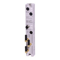
hilscher 1912.102 User Manual (146 pages)
netFIELD IO-Link Wireless Master PROFINET IO-Device
Brand:
hilscher
| Category:
Network Hardware
| Size: 3 MB
Table of Contents
Table of Contents
2
Table 1: List of Revisions
5
Introduction
5
List of Revisions
5
About this Document
5
Device Description
6
Functional Description
6
Device Overview
7
Figure 1: Device Overview, NFD-3090-PNS-IOLM\W
7
Table 2: Legend to the Device Overview, NFD-3090-PNS-IOLM\W
8
Table 7: Supply Voltage
8
Table 8: Ethernet
8
Table 105: Signs
8
Table 6: IO-Link Wireless Master
9
Table 5: Firmware
9
Table 4: Software
9
Table 3: Hardware
9
Product Software
9
Revisions and Versions
9
Identification
10
Figure 2: QR Code (Example)
10
Connectors and Interfaces
11
Power Supply
11
Ethernet
11
IO-Link, SMA Antenna
12
Derating
12
Figure 3: Derating Netfield IO-Link Wireless Master Device
12
Table 9: SMA Antenna Type
12
Personnel Qualification
13
Safety
13
Intended Use
13
General Note
13
Power Drop During Write and Delete Accesses in the File System
14
Exceeding the Maximum Number of Permitted Write and Delete Accesses
14
Information and Data Security
14
Getting Started
15
Table 10: Overview for Installation and Commissioning
15
Requirements
16
Hardware and System Requirements
16
Software Requirements
16
Mounting and Demounting
17
Mounting
17
Demounting
19
Grounding
19
Disposal of Waste Electronic Equipment
20
Connections
21
Connection Example
22
Figure 4: Connection Example with W-Bridge
22
Configuration
23
Configuration Tools
23
Table 11: Overview Tool Chains
25
Configuring PROFINET IO
27
Configuring Ports / Selecting Modules
28
Table 12: PROFINET Modules and Submodules
28
Table 13: Port Submodules (PDCT), and (Expert)
29
Setting Parameters
30
Table 14: Parameters of the Submodules IO-Link Wireless Device XX I / XX O + PQI (PDCT)
30
Table 15: Parameter IO-Link Wireless Master
31
Table 16: Parameters of the Submodules IO-Link Wireless Device XX I / XX O + PQI
33
Table 17: Calculation of the Port Cycle Time of the IO-Link Wireless Master
33
Table 18: Time Base of I-Am-Alive Time
34
Table 19: Calculation of I-Am-Alive Time
34
Configuration with Netfield Wireless Web Server
36
Functional Overview
36
Table 20: Functional Overview of the Netfield Wireless Web Server for IO-Link Devices
36
Open Netfield Wireless Web Server
37
Dashboard
38
Figure 5: Dashboard Page (Example)
38
Table 21: Data on "Dashboard" Page
38
Figure 6: Menu Item Signin - Input Mask for User Name and Password
39
Log in or User Administration
39
Licenses
39
Figure 7: User Administration Screen Mask (Initial State)
40
Figure 8: User Administration Screen Mask
41
Device Settings
42
Figure 9: Device Configuration Tab (Example)
42
Figure 10: Maintenance Information Tab
43
Table 22: Maintenance Information
43
Figure 11: Firmware Update Tab (Example)
44
Figure 12: Firmware Update Is Performed (Example)
46
Figure 13: Factory Reset Tab
47
Table 23: Options to Delete Settings
47
Figure 14: MQTT Tab, Client Status, Client Configuration Sub Tab (Example)
48
Table 24: MQTT in Port Configuration for IO-Link Device, Client Status
48
Table 26: MQTT in Port Configuration for IO-Link Device, Connection1 > IP Settings
49
Table 25: MQTT in Port Configuration for IO-Link Device, Client Configuration
49
Figure 15: MQTT Tab, Connection1 > IP Settings Sub Sub Tab (Example)
49
Figure 16: MQTT Tab, Connection1 > Session Settings Sub Sub Tab (Example)
50
Table 27: MQTT in Port Configuration for IO-Link Device, Connection1 > Session Settings
50
Figure 17: MQTT Tab, Connection1 > will Settings Sub Sub Tab (Example)
51
Table 28: MQTT in Port Configuration for IO-Link Device, Connection1 > will Settings
51
Figure 18: MQTT Tab, Connection1 > Advanced Settings Sub Sub Tab (Example)
52
IO-Link Wireless Master Settings
53
Figure 19: Channel Selection Tab
54
Table 30: IO-Link Wireless Master Settings - Channel Selection
54
Figure 20: Channel Selection Tab, Expert Settings (Example)
56
Figure 21: IO-Link Wireless Master > Configuration Tab
57
Table 31: IO-Link Wireless Master Settings - Configuration
57
Table 32: Scan Result, Pairing
59
Figure 23: "Scan Tab", Scan Result
59
Figure 22: Scan Tab
59
Device or Port Information, Pairing, IOLWD Update
61
Table 33: Information, Status, Settings, Pairing, IOLWD Update, ISDU, or Process Data
61
Figure 24: Information Tab, Device Information (Example)
62
Table 34: Information Tab, with Device Information
62
Figure 25: Status Tab, Port Status (Example)
63
Table 35: Port Status, Overview
63
Table 36: Port State, Possible Values
64
Figure 26: Settings Tab, Port Cycle Sub Tab (Example)
65
Table 37: Settings in Port Configuration for IO-Link Device, Port Cycle Sub Tab
65
Figure 27: Settings Tab, Validation Level Sub Tab (Example)
66
Table 38: Calculation of the Port Cycle Time of the IO-Link Wireless Master
66
Figure 28: Settings Tab, Transmission Sub Tab (Example)
67
Figure 29: Settings Tab, Miscellaneous Sub Tab (Example)
68
Figure 30: Pairing Tab after Port Mode was Set Correctly
70
Figure 31: Pairing Successfully Finished
71
Figure 32: IOLWD Update Tab, IOLWD Firmware Successfully Updated (Example)
73
Figure 33: Display of the on Request Data, Read/Write IO-Link Device Parameters
74
Figure 34: Display of the ISDU, Read/Write IO-Link Wireless Master Parameters
76
Figure 35: Display of the Process Data
79
Commissioning
80
Setting the IP Address
80
Figure 36: List of the Devices Found in the Local Network
80
Figure 37: IP Configuration Dialog
81
Configuration with Netfield Wireless Web Server
82
Configuring the IO-Link Wireless Master
83
Figure 38: IO-Link Wireless Master > Configuration Tab
83
Figure 39: Scan Tab
84
Figure 40: Scan Tab with Result
84
Port Settings for Commissioning
85
Figure 41: Settings Tab > Port Cycle Sub Tab (Example)
85
Figure 42: Settings Tab > Validation Level Sub Tab (Example)
86
Figure 43: Settings Tab > Transmission Sub Tab (Example)
87
Figure 44: Settings Tab > Miscellaneous Sub Tab (Example)
88
Testing
89
Figure 45: Tab and Table "Port Process Data" (Example PD Input Valid = OK)
89
Figure 46: Status Tab, Port Status
89
Figure 47: Information Tab, Device Information
90
Master Reset
91
Indexed Service Data Units
92
Figure 48: ISDU Tab, Read/Write IO-Link Device Parameters
92
Figure 49: ISDU Tab, Read/Write IO-Link Wireless Master Parameters
93
Table 102: OPC UA Server
94
Setting Date and Time
94
Wireless
94
Using OPC UA Client
95
Connecting with Device
95
Setting Date and Time of the Device Via OPC UA
97
Figure 50: Node Ntpclientupdateconfiguration (1)
97
Figure 51: Node Ntpclientupdateconfiguration (2)
98
Figure 52: Dialog for Configuring the NTP Client
98
Figure 53: Dialog for Configuring the NTP Client (Successful)
98
Communication
99
Process Data of the PROFINET IO-Device
99
Process Data of Submodule „IO-Link Wireless Master
99
Process Data of Submodules „IO-Link Wireless Device X I / X O + PQI
100
Process Data of Submodules „IO-Link Wireless Device X I + PQI
101
Process Data of Submodules „IO-Link Wireless Device X O + PQI
102
Port Qualifier Information
103
Provider and Consumer Status
103
Opc Ua
104
Figure 54: OPC UA: Information Model of the Device
104
Device Identification
105
Identification of Connected IO-Link Devices
105
NTP Client Configuration
106
MQTT Topics
107
General Parts of a Topic
107
Gateway Topics
107
Master Topics
109
Device Topics
113
Table 79: Device Process Data Output (JSON Object)
115
Table 80: Device Events (JSON Object)
115
Table 83: MQTT Connection Status, "JSON Key
116
Table 81: MQTT Topics
116
Table 82: MQTT Configuration, "JSON Key
116
MQTT Topics
116
Diagnosis
117
System LED
117
Table 84: States of the SYS-LED
117
Table 85: Definitions of the States of the SYS LED
117
Diagnosis Via Leds
117
Apl Led
118
Supply Voltage Status
118
Table 86: APL LED States
118
Table 87: Supply Voltage Status 1L and 2L
118
Table 89: Definition LED States Communication Status
119
Table 91: Definition LED States Ethernet Status
119
Table 88: Communication Status PROFINET IO-Device
119
PROFINET IO-Device Status
119
Table 90: Ethernet Status PROFINET IO-Device
119
Wireless Track Status
120
Wireless Port Status
120
Table 92: Wireless Track Status WT1
120
Table 93: Wireless Track Status WP01
120
Diagnosis over IO-Link
121
Event Qualifier
121
IO-Link Wireless Master Event Codes
121
Figure 55: Event Qualifier
121
Table 94: Event Qualifier
121
Table 95: IO-Link Wireless Master Event Codes
121
IO-Link Device Event Codes (Common)
122
Table 96: IO-Link Device Event Codes (Common)
122
Table 97: Technical Data NFD-3090-PNS-IOLM\W
124
Technical Data
124
Technical Data Device
124
Table 98: Technical Data SMA Antenna
125
Technical Data IO-Link Wireless Master
126
Technical Data Protocol
126
Table 99: Technical Data IO-Link Wireless Master
126
Table 100: Technical Data PROFINET IO-Device for the NFD-3090-PNS-IOLM\W Device
126
Technical Data Netfield Wireless Web Server
127
OPC UA Server
127
MQTT Client
127
Table 101: Technical Data Web Server
127
Table 103: Technical Data MQTT Client
127
Figure 56: Dimensions NFD-3090-PNS-IOLM\W Device
128
Dimensions Netfield IO-Link Wireless Master Device
128
Dimensions
128
Approvals
129
Fcc/Ised
129
Appendix
131
References
131
Conventions in this Manual
132
Table 104: Signal Words
132
Directives and Standards
133
Table 106: Directives and Standards Netfield IO-Link Wireless Master Device
133
Legal Notes
134
Registered Trademarks
138
List of Figures
139
Glossary
144
Contacts
146
Advertisement
Advertisement
Related Products
hilscher 1912.112
hilscher 1912.122
hilscher NT 100-RE-CC
hilscher NT 100-RE-RS
hilscher NT 100-DP-DP
hilscher NT 100-CO-RS
hilscher NT 100-DN-CC
hilscher NT 100-DN-CO
hilscher NT 100-DN-DP
hilscher NT 100-DN-DN
hilscher Categories
Gateway
Computer Hardware
Network Hardware
Motherboard
PCI Card
More hilscher Manuals
Login
Sign In
OR
Sign in with Facebook
Sign in with Google
Upload manual
Upload from disk
Upload from URL