Sign In
Upload
Manuals
Brands
Hill-Rom Manuals
Medical Equipment
Trumpf Medical TruLight 5000
Hill-Rom Trumpf Medical TruLight 5000 Manuals
Manuals and User Guides for Hill-Rom Trumpf Medical TruLight 5000. We have
1
Hill-Rom Trumpf Medical TruLight 5000 manual available for free PDF download: Instruction Manual
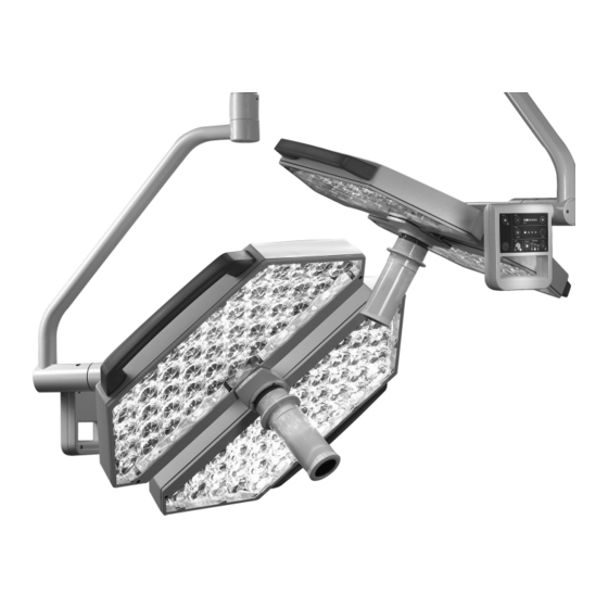
Hill-Rom Trumpf Medical TruLight 5000 Instruction Manual (92 pages)
Lighting System
Brand:
Hill-Rom
| Category:
Medical Equipment
| Size: 6 MB
Table of Contents
Table of Contents
6
Important Information Regarding Safe Use
10
Details for the Identification of the System
10
Details for Identification of the Instruction Manual
10
Designation of Groups of Individuals
10
Operator
10
User
10
Specialist Personnel
10
Information for Operators
10
Initial Commissioning
11
Availability of the Instruction Manual
11
Guarantee
11
Maintenance and Repair
11
Service Life of the Device
11
Date of Manufacture
11
Delivery
12
Transportation Damage
12
Return Address
12
Information for Users
12
Training for Use of the Device
12
Obligation of the User to Inform and to Inspect
12
Purpose of the Device
12
Identification
12
Standards and Directives
13
Internationally Applied Standards
13
Intended Use
13
Special Features
14
Improper Use
14
Ambient Conditions for Operation and Storage
14
Ambient Conditions for Operation
14
Ambient Conditions for Storage
14
Combination with Other Medical Devices
15
Disposal
15
Safety Instructions
16
Structure of the Safety Instructions in this Instruction Manual
16
Indicating Risk of Injury
16
Indicating Damage to Property
16
Indicating Additional Information
16
Additional Symbols for the Safety Information
16
Symbols on the Device
17
Overview of the most Important Safety Instructions
17
The Technology of the Lighting System
22
The Light Head
22
The LED Light Source
23
Accessories
23
Identification of the Lighting System
24
Use of Serial Numbers
24
Position of the Serial Numbers on the Ceiling-Mounted Version
24
Position of the Serial Numbers on the Wall-Mounted Version
24
Position of the Serial Numbers on the Mobile Stand Version
25
Position of the Laser Marking
25
Description of Devices and Functions
26
Description of the Ceiling-Mounted Version
26
Implementation of the Ceiling-Mounted Version
26
Components of the Ceiling-Mounted Version
26
Camera on Light Head, Optional
26
Size of the Light Heads
26
Rotation / Swivel Ranges of the Ceiling-Mounted Version
27
Description of the Wall-Mounted Version
28
Implementation of the Wall-Mounted Version
28
Components of the Wall-Mounted Version
28
Size of the Light Heads
28
Rotary / Swivel Movement of the Wall-Mounted Version
29
Description of Mobile Stand Version
30
Implementation of the Mobile Stand Version
30
Components of the Mobile Stand Version
30
Power Supply of the Mobile Stand Version
30
Size of the Light Heads
30
Rotating / Swivel Movement of the Mobile Stand Version
31
Functional Specifications of the Light Head
32
Positioning the Light Head
32
Operating the Light Heads
32
Controlling the Light Intensity
34
Sterile Light Control (SLC) Function, Optional
35
Adaptive Light Control (ALC) Function, Optional
36
Adaptive Light Control Plus (ALC Plus) Function, Optional
37
Controlling the Light Field
38
Controlling the Colour Temperature (Optional)
39
Synchronisation of the Colour Temperature
40
Commissioning
41
Checking the Lighting Systems
41
Positioning of the Lighting Systems
42
Risks of Collision During Positioning
42
Positioning the Cover-Mounted / Wall-Mounted Version
43
Positioning the Mobile Stand Version
45
Connecting the Mobile Stand Version to the Mains
46
Decommissioning
47
Switching off the Ceiling- and Wall-Mounted Version
47
Switch off the Mobile Stand Version
47
Operation
48
Working Rules
48
Preparatory Measures
48
Measures to Take When Using the Lighting System
49
Attaching the Sterile Handle
50
Control Panels of the Lighting System
51
Switching the Light Head On/Off
52
Disconnecting the Power to the Lighting System
52
Setting the Size of the Light Field
53
Setting the Light Intensity
54
Non-Sterile Setting of the Light Intensity at the Control Panel
54
Set the Light Intensity in the Sterile Area Using the Sterile Light Control (SLC)
55
Setting the Light Intensity to the Working Distance in the Non-Sterile Area with Adaptive Light Control (ALC)
56
Adjusting the Light Intensity with Adaptive Light Control Plus (ALC Plus)
57
Setting Colour Temperature
59
Synchronisation of the Colour Temperature
59
Cleaning and Disinfection
60
Cleaning and Disinfection
61
General
61
Wipe-Over Disinfection
61
Recommended Disinfectants
62
Sterilising Handles of Surgical Lights
63
Preparation
63
Cleaning and Disinfection
63
10.2.1 Cleaning
63
10.2.2 Disinfection
63
Sterilisation
64
10.3.1 General Information
64
10.3.2 Steam Sterilisation
64
10.3.3 Sterilisation Packaging
65
Inspections, Maintenance and Repairs
66
Inspections During Operation
66
Annual Visual Inspection
66
Maintenance Every Two Years
67
Repairs
67
Adjustments
68
Setting Spring Arm Swivel Range Type AC 2000 LCH
68
Disconnecting the Power to the Lighting System
68
12.1.2 Setting the Swivel Range
68
Setting Spring Arm Swivel Range Type AC 2000 and Type AC 3000
69
Disconnecting the Power to the Lighting System
69
Setting the Swivel Range
69
Setting Spring Arm Swivel Range Type AC 5000
70
Disconnecting the Power to the Lighting System
70
12.3.2 Removing the Covers
70
12.3.3 Setting the Swivel Range
70
12.3.4 Installing the Covers
70
Setting Spring Arm Spring Force Type AC 2000 LCH
71
Disconnecting the Power to the Lighting System
71
Adjusting the Spring Force
71
Setting Spring Arm Spring Force Type AC 2000 and Type AC 3000
72
Disconnecting the Power to the Lighting System
72
12.5.2 Adjusting the Spring Force
72
Setting the Spring Arm Spring Force Type AC 5000
73
Disconnecting the Power to the Lighting System
73
12.6.2 Adjusting the Spring Force
73
Adjusting the Brake Force of the Friction Brakes
74
Disconnecting the Power to the Lighting System
74
12.7.2 Adjusting the Braking Force for the Boom
74
Adjusting the Braking Force for the Spring Arm
75
Adjusting the Brake of the Convenience Bracket on AC 3000
75
Adjusting the Brake Force of the Cardan Joint Rod
76
Setting the Braking Force of the Cardan Joint Axle on the Standard Light Head
77
Setting the Braking Force on the Light Head SLC / ALC Plus
78
Setting the Cardan Joint Axis Braking Force on the Standard Light Head with Camera
79
Consumables
80
Troubleshooting
81
Technical Data
82
Equipment Versions for the Light Models
82
Device Data
82
EMC Information
86
Advertisement
Advertisement
Related Products
Hill-Rom Trumpf Medical TruLight 1000
Hill-Rom Trumpf Medical TruLight 3000
Hill-Rom Liko HygieneVest 55
Hill-Rom Liko HygieneVest 50
Hill-Rom 100
Hill-Rom 2000014
Hill-Rom 2000015
Hill-Rom 2000019
Hill-Rom 20090059
Hill-Rom 2020003
Hill-Rom Categories
Medical Equipment
Lifting Systems
Sling
Mobility Aid
Indoor Furnishing
More Hill-Rom Manuals
Login
Sign In
OR
Sign in with Facebook
Sign in with Google
Upload manual
Upload from disk
Upload from URL