Sign In
Upload
Manuals
Brands
HF Manuals
Control Unit
HF-BL200A-0
HF HF-BL200A-0 Manuals
Manuals and User Guides for HF HF-BL200A-0. We have
2
HF HF-BL200A-0 manuals available for free PDF download: User Manual
HF HF-BL200A-0 User Manual (51 pages)
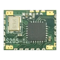
Bluetooth Low Energy BLE 4.1 Module
Brand:
HF
| Category:
Control Unit
| Size: 1 MB
Table of Contents
Table of Contents
2
List of Figures
5
List of Tables
5
Product Overview
7
General Description
7
Device Feature
7
Key Application
7
Device Parameter
8
Order Information
8
Table 1 HF-BL200A Module Technique Specification
8
Figure 1. HF-BL200A Order Information
9
Hardware Introduction
10
Pin Definition
10
Figure 2. HF-BL200A Pin Definition
10
Table 2 HF-BL200A Pin Function Definition
10
Electrical Specification
12
Table 3 Limited Specification
12
Table 4 Electrical Specification
12
Table 5 RF Specification
12
Mechanical Size
13
Figure 3. HF-BL200A-0 Mechanical Size
13
Antenna Layout
14
Figure 4. HF-BL200A-1 Mechanical Size
14
Figure 5. HF-BL200A Module Reference Placement
15
Uart Transparent Transmit Mode
16
Transparent Transmit Mode
16
Figure 6. Basic HF-BL200A Wireless Network Structure
16
Table 8 Module Connect Interval 20Ms Communication Mode Example
17
Transparent Transmit Mode Pin Description
18
Factory Default Parameter
19
Device Name
19
Broadcast Parameter
19
Transmit Power
19
Connect Parameter
19
Baud Rate
19
Send Latency Parameter
19
Uart at Command Definition
20
Module Operation Mode Configure
20
At:command Overview
20
Figure 7. HF-BL200A Default UART Parameter
20
Command Format
21
Figure 8. "AT:HELP" List All Command
21
Command List
22
Table 9 Error Code List
22
Table 10 at Command List
22
AT Command
24
Help Command
24
Set Module NAME
24
Query Module Name
25
Set Connect Parameter
25
Query Connect Parameter
26
Set Baud Rate
27
Query Baud Rate
27
Get MAC Address
28
Query Software Version
28
Set Transmit Power
28
Query Transmit Power
29
Set Broadcast Parameter
30
Query Broadcast Parameter
30
Set User-Define Broadcast Data
31
Query User-Define Broadcast Data
31
Set Auto-Broadcast Switch
32
Query Auto-Broadcast Switch
32
Start Broadcast
33
Stop Broadcast
33
Query Current BLE Subsystem Status
34
Disconnect
34
Set Device Verify Code
35
Query Device Verify Code
35
Set UART Output Data Latency
36
Save Parameter
37
Module Restore
37
Figure 9. Module UART Output Data Latency Set Map
37
Set Module Operate Mode
38
Module BLE Subsystem Status Notification
38
Module CPU Status Notification
39
Restore Factory Setting Via at Command
39
Enable Module Deep Sleep
39
Restore Factory Setting Via Hardware Method
40
Figure 10. Module UART Receive Enable Signal Map
40
App Command
41
Channel and Data Description
41
Data Format
41
Table 11 Command Data from APP to Module
41
Table 12 Feedback Data from Module to APP
41
Command Content
42
Command Type:0X0E
42
Command Type:0X0F
42
Table 13 Command Type 0X0F Command List
42
Table 14 Command Type 0X0F Feedback List
43
Basic Communication Mechanisim
44
Application Service Data Channel(User-Define Application Service Uuid:0X2B00
44
Module->APP, UART Data Channel【Feature Uuid:0X2B10
44
APP->Module,Uart Data Channel【Feature Uuid:0X2B11
44
Table 15 Description of User-Define Service of All Channnel
44
Table 16 0X2B10 Feature UART Module->APP Channel Description
44
Table 17 0X2B11 Feature UART APP->Module Channel Description
44
APP->Module,Ota Mode Switch【Feature Uuid:0X2B12
45
APP->Module,App Command Channel【Feature Uuid:0X2B13
45
Battery Service Data Channel
45
Table 18 0X2B12 Feature OTA Mode Switch Channel Description
45
Table 19 0X2B13 Feature APP Command Channel Description
45
Table 20 Description of Battery Service of All Channel
45
APP->Module,Battery Data Channel 【Feature Uuid:0X2A19
46
OTA Service Data Channel
46
APP->Module,Ota Data Channel
46
Table 21 0X2A19 Feature Battery Power Channel Feature Description
46
Table 22 Description of OTA Service of All Channel
46
Table 23 Feature OTA Data Channel Feature Description
46
Package Information
47
Reflow Soldering Profile
47
Handling Instruction
47
Figure 11. Reflow Soldering Profile
47
Table 24 Reflow Soldering Specification
47
Shipping Information
48
Figure 12. Package Information
48
Appendix A: Uart Transparent Transmit Typical Application
49
Figure 13. UART Transparent Transmit Typical Application
49
Advertisement
HF HF-BL200A-0 User Manual (51 pages)
Bluetooth Low Energy (BLE 4.1) Module
Brand:
HF
| Category:
Control Unit
| Size: 1 MB
Table of Contents
Table of Contents
2
List of Figures
5
List of Tables
5
Product Overview
7
General Description
7
Device Feature
7
Key Application
7
Device Parameter
8
Order Information
8
Table 1 HF-BL200A Module Technique Specification
8
Figure 1. HF-BL200A Order Information
9
Hardware Introduction
10
Pin Definition
10
Figure 2. HF-BL200A Pin Definition
10
Table 2 HF-BL200A Pin Function Definition
10
Electrical Specification
12
Table 3 Limited Specification
12
Table 4 Electrical Specification
12
Table 5 RF Specification
12
Mechanical Size
13
Figure 3. HF-BL200A-0 Mechanical Size
13
Antenna Layout
14
Figure 4. HF-BL200A-1 Mechanical Size
14
Figure 5. HF-BL200A Module Reference Placement
15
Uart Transparent Transmit Mode
16
Transparent Transmit Mode
16
Figure 6. Basic HF-BL200A Wireless Network Structure
16
Table 8 Module Connect Interval 20Ms Communication Mode Example
17
Transparent Transmit Mode Pin Description
18
Factory Default Parameter
19
Device Name
19
Broadcast Parameter
19
Transmit Power
19
Connect Parameter
19
Baud Rate
19
Send Latency Parameter
19
Uart at Command Definition
20
Module Operation Mode Configure
20
At:command Overview
20
Figure 7. HF-BL200A Default UART Parameter
20
Command Format
21
Figure 8. "AT:HELP" List All Command
21
Command List
22
Table 9 Error Code List
22
Table 10 at Command List
22
AT Command
24
Help Command
24
Set Module NAME
24
Query Module Name
25
Set Connect Parameter
25
Query Connect Parameter
26
Set Baud Rate
27
Query Baud Rate
27
Get MAC Address
28
Query Software Version
28
Set Transmit Power
28
Query Transmit Power
29
Set Broadcast Parameter
30
Query Broadcast Parameter
30
Set User-Define Broadcast Data
31
Query User-Define Broadcast Data
31
Set Auto-Broadcast Switch
32
Query Auto-Broadcast Switch
32
Start Broadcast
33
Stop Broadcast
33
Query Current BLE Subsystem Status
34
Disconnect
34
Set Device Verify Code
35
Query Device Verify Code
35
Set UART Output Data Latency
36
Save Parameter
37
Module Restore
37
Figure 9. Module UART Output Data Latency Set Map
37
Set Module Operate Mode
38
Module BLE Subsystem Status Notification
38
Module CPU Status Notification
39
Restore Factory Setting Via at Command
39
Enable Module Deep Sleep
39
Restore Factory Setting Via Hardware Method
40
Figure 10. Module UART Receive Enable Signal Map
40
App Command
41
Channel and Data Description
41
Data Format
41
Table 11 Command Data from APP to Module
41
Table 12 Feedback Data from Module to APP
41
Command Content
42
Command Type:0X0E
42
Command Type:0X0F
42
Table 13 Command Type 0X0F Command List
42
Table 14 Command Type 0X0F Feedback List
43
Basic Communication Mechanisim
44
Application Service Data Channel(User-Define Application Service Uuid:0X2B00
44
Module->APP, UART Data Channel【Feature Uuid:0X2B10
44
APP->Module,Uart Data Channel【Feature Uuid:0X2B11
44
Table 15 Description of User-Define Service of All Channnel
44
Table 16 0X2B10 Feature UART Module->APP Channel Description
44
Table 17 0X2B11 Feature UART APP->Module Channel Description
44
APP->Module,Ota Mode Switch【Feature Uuid:0X2B12
45
APP->Module,App Command Channel【Feature Uuid:0X2B13
45
Battery Service Data Channel
45
Table 18 0X2B12 Feature OTA Mode Switch Channel Description
45
Table 19 0X2B13 Feature APP Command Channel Description
45
Table 20 Description of Battery Service of All Channel
45
APP->Module,Battery Data Channel 【Feature Uuid:0X2A19
46
OTA Service Data Channel
46
APP->Module,Ota Data Channel
46
Table 21 0X2A19 Feature Battery Power Channel Feature Description
46
Table 22 Description of OTA Service of All Channel
46
Table 23 Feature OTA Data Channel Feature Description
46
Package Information
47
Reflow Soldering Profile
47
Handling Instruction
47
Figure 11. Reflow Soldering Profile
47
Table 24 Reflow Soldering Specification
47
Shipping Information
48
Figure 12. Package Information
48
Appendix A: Uart Transparent Transmit Typical Application
49
Figure 13. UART Transparent Transmit Typical Application
49
Advertisement
Related Products
HF HF-BL200A-1
HF HF-BL200A
HF HF-BL100-CU
HF HF-LPS170
HF HF2111A
HF HF-LPT130B
HF HF-LPT330
HF HF-LPD130
HF HF2211S
HF HF9624
HF Categories
Indoor Furnishing
Network Hardware
Control Unit
Wireless Router
Network Router
More HF Manuals
Login
Sign In
OR
Sign in with Facebook
Sign in with Google
Upload manual
Upload from disk
Upload from URL