Sign In
Upload
Manuals
Brands
Heathkit Manuals
Transceiver
HW-101
Heathkit HW-101 Manuals
Manuals and User Guides for Heathkit HW-101. We have
6
Heathkit HW-101 manuals available for free PDF download: User Manual, Manual, Troubleshooting Manual, Assembly And Operation Manual, Optimization Manual, Installation Manual
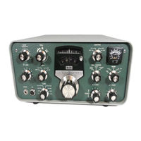
Heathkit HW-101 User Manual (246 pages)
SSB
Brand:
Heathkit
| Category:
Transceiver
| Size: 18 MB
Table of Contents
Table of Contents
6
Parts Packaging
8
Circuit Board Assembly
9
Switch Boards
10
Parts List #1
10
Step-By-Step Assembly
12
Crystal Switch Board Assembly
12
Heterodyne Oscillator Switch Board Assembly
13
Driver Grid Switch-Board Assembly
14
Drive Plate Switch-Board Assembly
15
Modulator Circuit Board
16
Parts List #2
16
Modulator Circuit Board Assembly
18
IF Circuit Board
21
Parts List #3
21
IF Circuit Board Assembly
22
Bandpass Circuit Board
24
Parts List #4
24
Bandpass Circuit Board Assembly
25
Audio Circuit Board
28
Parts List #5
28
Audio Circuit Board Assembly
29
RF Drive Circuit Board
32
Parts List #6
32
RF Drive Circuit Board Assembly
33
Vfo
35
Parts List #7
35
VFO Assembly
36
VFO Parts Pictorial
37
VFO Parts Mounting
38
Chassis Photo
39
Pictorial 7-1
40
Pictorial 7-3
44
Pictorial 7-2
49
Pictorial 7-4
50
Chassis
51
Parts List #8
51
Chassis Parts Pictorial
52
Chassis Parts List
54
Chassis Assembly
59
Pictorial 8-1
60
Detail 8-1E
62
Detail 8-1G
62
Detail 8-1F
62
Detail 8-2A
63
Detail 8-2B
63
Detail 8-2C
63
Detail 8-2D
63
Detail 8-2E
64
Detail 8-2F
64
Detail 8-2G
64
Detail 8-2J
65
Detail 8-2H
65
Detail 8-2K
66
Detail 8-2L
66
Detail 8-2M
66
Pictorial 8-2
67
Pictorial 8-3
69
Detail 8-3A
69
Pictorial 8-4
70
Detail 8-3B
72
Detail 8-3C
72
Pictorial 8-3 (Repeat)
73
Detail 8-3D
73
Detail 8-3E
74
Detail 8-3F
74
Detail 8-3G
74
Harness Wiring
75
Detail 8-4A
76
Detail 8-4B
79
Detail 8-4C
79
Chassis Bottom-Components and Wiring
81
Detail 8-5B
82
Detail 8-5C
84
Pictorial 8-5
85
Coaxial Cable Wiring
87
Detail 8-6A
87
Detail 8-6B
87
Pictorial 8-6
89
Detail 8-6C
90
Detail 8-6D
90
Detail 8-6E
90
Detail 8-6F
90
Component Mounting-Chassis Bottom
91
Detail 8-6G
92
Detail 8-6H
92
Detail 8-6J
92
Detail 8-6K
93
Detail 8-6L
94
Pictorial 8-7
95
Detail 8-7A
95
Wiring RF Section-Chassis Top
96
Pictorial 8-8
96
Detail 8-8A
96
Pictorial 8-8 (Repeat)
97
Detail 8-8B
97
Detail 8-8C
98
Detail 8-8D
98
Pictorial 8-9
99
Detail 8-9A
99
Mounting Parts-Front Panel
100
Pictorial 8-10
101
Front Panel Wiring
103
Pictorial 8-13
104
Pictorial 8-14
105
Pictorial 8-11
106
Pictorial 8-12
108
Front Panel Mounting
109
Detail 8-13A
109
Detail 8-13B
109
Wiring-Chassis Top
110
Detail 8-14A
111
Detal 8-14B
111
Detail 8-14C
112
Detail 8-15B
113
Detail 8-15C
113
Detail 8-15D
113
Detail 8-15E
114
Detail 8-15F
114
Detail 8-15G
114
Pictorial 8-15
115
Detail 8-15A
116
Final Wiring-Chassis Bottom
117
Detail 8-16A
117
Pictorial 8-16
118
Pictorial 8-16B
119
Detail 8-16C
120
Detail 8-17A
121
Pictorial 8-17
122
Pictorial 8-18
124
Detail 8-19B
125
Detail 8-19C
125
Detail 8-19D
126
Detail 8-19E
126
Detail 8-19F
127
Knob Installation
128
Pictorial 8-20
128
Detail 8-20A
128
Pictorial 8-19
129
Detail 8-19A
130
Figure 1-1
132
Figure 1-2
133
Control and Connector Functions
134
Front Panel Functions
134
Driver Preselector
134
Final Tune and Load
134
Mode, Band, Main Tuning
135
Zero Set, Function
135
Filter, RF Gain, Meter
135
AF Gain
135
Right Side Control Functions
136
Top Chassis Control Functions
136
Vox Sens, Vox Delay
136
Anti-Trip, Zero Adjust, Bias
136
Rear Apron Connections
137
Preliminatry Checks
138
Meter Circuit Checks
138
Resistance Checks
139
Figure 1-4
139
Figure 1-3
140
Ohmmeter Test Points Table
142
Pictorial 8-21
145
Detail 8-21A
145
Detail 8-21B
145
Coil Cover and Tube Installation
146
Power Supply Connections
147
HP-13 Series Power Supply Connections
147
Figure 1-5
148
HP/PS-23 Series Power Supply Connections
149
Figure 1-6
149
Microphone Connections
150
Heath Microphones
150
Other Microphones
150
Initial Test
152
Alignment
154
S Meter Adjustment
154
Receiver Alignment
155
VFO Alignment
156
Drive Grid and Plate Coils
156
Transmitter Alignment
157
Crystal Calibrator Alignment
159
Dial Calibration
160
VFO Shifter Adjustment
160
Cabinet Installation
162
To Complete the Transceiver Assembly
164
Figure 1-12
165
Installation
166
Fixed Station Installation
166
Linear Amplifier Consideratons
167
Antenna Relay Connections
167
Heath Amplifiers
167
T-Pad
167
Figure 1-15
168
Figure 1-16
168
Mobile Installation
169
Mobile Antennas
169
Typical Tuning Procedure
169
Determining SWR
170
Adjusting Antenna Length
170
Noise Suppression Troubleshooting Chart
171
Noise Suppression
172
Figure 1-18
173
Operation
174
Reading the Meter
174
Reading the Dial
174
Receiver Section
175
Transmitter Section
175
Initial Tune up
175
CW Operation
176
Cross-Mode Operation
176
Single Sideband Operation
177
PTT Adjustment
177
Operation with a Linear Amplifier
177
Vox Adjustments
177
Mobile Operation
178
Figure 1-17
180
In Case of Difficulty
181
Transmitter Voltage Chart - Figure 1-21
182
Receiver DC Voltage Chart - Figure 1-20
183
Receiver Voltage Chart Notes
184
Signal Voltages
184
RF Voltage Servicing
185
VFO Troubleshooting
185
Troubleshooting Chart
186
VFO Troubleshooting (2)
194
VFO Assembly Removal
194
VFO Assembly Replacement
194
VFO Troubleshooting Chart
195
VFO RF Troubleshooting
195
Resistance Chart - Figure 1-22
196
VFO Voltage Chart - Figure 1-23
197
Block Diagram
200
Specifications
201
Receiver Specifications
201
Transmitter Specifications
201
General Specifications
202
Circuit Description
205
Transmitter Circuits
206
Relay and Vox Amplifier
206
Figure 2-3
207
Figure 2-4
207
Anti-Trip Circuit
208
Speech Amplifier and Cathode Follower
208
Carrier Oscillator
209
Balanced Modulator
210
Isolation Amplifier
210
Crystal Filter
210
IF Amplifier
211
VFO Info
212
First Transmitter Mixer
212
Heterodyne Oscillator and Cathode Follower
213
Second Transmitter Mixer
214
Driver
214
Final Amplifiers
214
ALC Circuit
215
Tone Oscillator and Amplifier
216
CW Operation (Full Schematic)
216
Figire 2-17
218
T-R Switching
220
Figure 2-19
222
Figure 2-21
222
Receiver Circuits
223
RF Amplifier
223
First and Second Receiver Mixers
224
IF Amplifiers
224
AVC Circuits
224
Figure 2-23
225
Figure 2-24
225
Product Detector
226
Audio and Power Amplifiers
226
Crystal Calibrator
227
Metering Circuits
228
Figure 2-28
229
Chassis Photographs
230
Circuit Board X-Ray Views (Viewed from Foil Side)
234
Bandpass Circuit Board View
234
Crystal Switch-Board
234
Modulator Circuit Board View
236
Heterodyne Oscillator Switch-Board
236
Driver Plate Switch-Board
236
Audio Circuit Board View
237
Phase Shift Circuit Board
237
Driver Grid Switch-Board
237
Parts Identification
238
Inductor Cross Reference Table
238
Schematic of the Heathkit SSB Transceiver Model HW-101
239
Advertisement
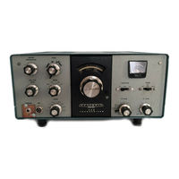
Heathkit HW-101 Troubleshooting Manual (190 pages)
Brand:
Heathkit
| Category:
Transceiver
| Size: 4 MB
Table of Contents
Heathkit HW-101 and SB-10X Restoration and Troubleshooting
1
Table of Contents
3
A)History of the HW-101
14
A.1.The SB-Series and HW-Series (Wikipedia)
15
A.2.Comparison of Various Models
16
A.3.Sb Series Vs HW Series
16
A.3.1.Rf Amp and 1St Receiver Mixer
17
A.3.2.Sb-101/SB-102 LMO Power Source
18
A.3.3.Sideband Bias Circuit
18
A.3.4.Accessory Socket
18
A.3.5.Cw Filter
18
A.3.6.Sb-102 Vs. HW-101
19
A.3.7.Power Supply
20
B)General Inspection and Restoration Checklist
21
B.1.Initial Inspection and Cleaning
21
B.2.Resistance and Voltage Checks
23
B.3.Receiver Alignment
24
B.4.Transmit Alignment
24
B.5.Meter Checks
24
B.6.Final Checks (Optional)
24
C)General Troubleshooting Tips
26
C.1.The Unit Appears Completely Dead
26
C.2.Does the Unit Receive
26
C.2.1.Unit Does Not Receive at All
26
C.2.2.Unit Receives on some Bands but Not Others
27
C.3.Transmitter Troubleshooting
27
D)Transmit Tuning and Operation
28
D.1.Initial Transmit Tune-Up
28
D.2.Single Sideband Operation
29
D.2.1.Ptt Adjustments
29
D.2.2.Vox Adjustments
29
D.3.Cw Operation
30
E)Alignment
32
S.2.1.Final Heterodyne Oscillator Alignment
38
S.2.2.Driver Neutralization Adjustment
38
S.3.Lmo Shifter Adjustment
39
T)Uneven Response Across the Band / Bandpass Filter
40
To 8895 Khz Bandpass Filter
40
T.1.1.Measuring the Bandpass Filter Response (Simple Method)
41
T.1.2.Measuring the Bandpass Filter Response (Sweep Analysis)
41
U)Signal Level Measurements
44
U.1.Receive Signal Levels
44
U.1.1.Carrier and Heterodyne Oscillator Levels
44
U.1.2.Receive Audio Signal Levels
45
Levels)
45
V)Using an Audio Signal Generator at 1 Khz, Connect the Generator to the Top of the AF Gain Control and Adjust the AF Gain Control to Provide 500 Mw Audio Output
45
V.1.1.Receive RF and if Signal Levels
45
V.2.Transmit Signal Levels
49
V.2.1.Transmit and VOX Audio Level Troubleshooting Guide
49
V.2.2.Transmit RF Signal Levels
50
W)Signal to Noise Ratio (SNR)
52
W.1.Signal to Noise Ratio (Theory)
52
W.1.1.Concept of Signal to Noise Ratio SNR
52
W.1.2.Signal to Noise Ratio
52
W.1.3.Effect of Bandwidth on SNR
53
W.1.4.Signal to Noise Ratio Specifications
53
W.2.Measuring Signal to Noise Ratio (SNR)
54
W.2.1.Required Equipment
54
W.2.2.Test Setup
55
W.2.3.Test Methodology
55
X)Testing Gain, S+N/N, AGC Threshold and Figure of Merit
58
X.1.Testing
59
X.1.1.Receiver Gain
59
S+N)/N Testing
59
X.1.3.Agc Threshold
59
X.1.4.Agc Figure of Merit
60
X.2.Summation
60
Y)Heathkit "S" Meter Circuit
61
Y.1."S" Meter Vs. AVC Voltage
62
Y.2.Avc and "S" Meter Calibration
63
Z)Servicing Procedures
64
Z.1.Front Panel Remove and Replace
64
Z.1.1.Front Panel Removal
64
Z.1.2.Front Panel Installation
65
After the Panel Is Installed
65
After the Panel Is in Place
65
A)During this Procedure, be Especially Careful Not to Place too Much Pressure on the Main Tuning Dial
66
B)During this Procedure, be Especially Careful Not to Place too Much Pressure on the Zero Set Shaft
66
Z.2.Front Panel Escutcheon Mounting
67
Z.3.Sb Series Dial Mechanism
69
Z.3.1.Installation of the Spiral Groove Follower Mechanism
69
Z.3.2.Installation of Circular Dial on LMO Shaft
69
Down. Retighten the Screws
70
Drive Arm Base up or Down. Retighten the Screws
70
Pointer Is at the "5" Marking. Retighten the Screws
71
The Dial Pointer Is at the "5" Marking. Retighten the Screws
71
Ab.1.1.Dial Calibration
71
Ab.1.2.Re-Engaging the Main Tuning Pulley
71
Ab.1.3.Drag When Rotating Main Tuning Knob
73
Ab.1.4.Circular Dial Wobble
74
Ab.1.5.Spiral Groove Nylon Follower Replacement
75
Ab.1.6.Zero Set Dial Mechanism and Pulley
76
Ab.1.7.Repairing the Center Hub
78
Ab.2.Knob Inlays
80
Ab.3.Pa Load Capacitor Remove and Replace
81
Ab.4.Function Switch (A.C. Switch)
82
Ab.4.1.Finding a Replacement AC Switch
82
Ab.4.2.Replacing the AF Gain with a Control Having an AC Switch
82
Ab.4.3.Modifying the Failed Switch with a Microswitch
82
Ac)Modifications
84
Ac.1.Conversion to Low-Z Headphones
85
Ac.2.Improved CW Operation
86
Ac.3.Transmit Improvements
88
Ac.4.Receive Improvements
90
Ac.5.Bfo Level to Product Detector
90
Ac.6.I.f. Filter Passband Improvements
92
Ac.7.Stabilizing Meter Zero Settings
94
Ac.8.Antenna Connector
96
Ac.8.1.Bnc Connector
96
Ac.8.2.So-239 Connector
96
Ac.8.3.So-239 to RCA Male Adapter
97
Ac.9.Sb-100 CW Filter Modification
98
Ac.10.Using an External VFO for Split Frequency Operation
100
Ad)Heathkit Filters
101
Ad.1. Heathkit Filter Measurements
102
Ad.2.Ssb Filter 404-200 Circuit
104
Ad.3.Ssb Filter 404-283 Circuit
105
Ae)Printed Circuit Boards (Pcbs)
107
Ae.1.Modulator Printed Circuit Board 85-127-X
109
Ae.1.1.85-127P221 (SB-100, SB-101)
109
Ae.2.If Printed Circuit Board 85-128-X
110
Ae.3.Bandpass Printed Circuit Board 85-129-X
111
Ae.3.1.85-129P223 (SB-100)
111
Ae.4.Audio Printed Circuit Board 85-130-X
112
Ae.4.1.85-130P224 (SB-100, SB-101)
112
Ae.5.Rf Driver Printed Circuit Board 85-131-X
113
Ae.6.Crystal Switch Board 85-132-X
114
Ae.7.Het Osc, Driver Grid, and Driver Plate Switch Board 85-133-X
115
Af)Heathkit Linear Master Oscillators (Lmos)
116
Af.1.Lmo Part Numbers & Usage
116
Af.1.1.Heathkit TRW LMO
117
Af.1.2.Lmo Part Number 110-13
118
Af.1.3.Lmo Part Number 110-32
119
Af.1.4.Lmo Part Number 110-40
120
Af.1.5.Sb-102 LMO (Ver6)
121
Af.2.Lmo Repair and Service Notes
122
Af.2.1.Lmo Remove and Replace
122
Af.2.2.Heath Tube-Type LMO Repair
124
Af.2.3.Photos Showing Added Grounding Braid
127
Af.2.4.Repairing and Recalibrating a Stuck LMO
130
Af.2.5.Heathkit SB-102 Transceiver LMO Stability Fix
132
Ag)Matching Heathkit Paint
133
Ag.1.1.Matching Heathkit Paint: Part 1
133
Ag.1.2.Matching Heathkit Paint: Part 2
134
Ag.1.3.Matching Heathkit Paint: Part 3
135
Ah)Hw-101 and SB-10X Service Bulletins
136
Ah.1.Hw-101 Service Bulletins
136
Ah.1.1.Hw-101-1: VFO Drift
136
Ah.1.2.Hw-101-2: Repeated Heterodyne Oscillator Tube Failure Inadequate USB-LSB Frequency Shift
136
Ah.1.3.Hw-101-3: Carrier Null Control Failure
136
Ah.1.4.Hw-101-4: Low Output on 40 Meters
136
Ah.1.5.Hw-101-4: Low Output on 40 Meters
137
Ah.1.6.Hw-101-5: Alternate Method of Neutralizing the Final Amplifiers
137
Ah.1.7.Hw-101-5: Alternate Method of Neutralizing the Final Amplifiers
137
Ah.1.8.Hw-101-6: SB & HW Series Audio Preamplifier & VOX Circuit Troubleshooting Guide
138
Ah.1.9.Hw-101-7: SB & HW Series Instability & Corrective Information
138
Ah.1.10.Hw-101-8: Oscillations or Low Drive
138
Ah.1.11.Hw-101-9: Self Oscillations Occurring after Installation of Steel Comb Brackets
139
Ah.1.12.Hw-101-10: S-Meter Drift
139
Ah.1.13.Hw-101-11: Low Receiver Sensitivity
139
Ah.1.14.Hw-101-12: Improperly Manufactured 6HS6 Tubes
139
Ah.1.15.Hw-101-13: Germanium Diode Change
139
Ah.1.16.Hw-101-14: Improve ALC Adjustment
140
Ah.1.17.Hw-101-15: Driver and Mixer Switch Shields will Not Take Solder
140
Ah.1.18.Hw-101-16: Side Tone too Loud
140
Ah.1.19.Hw-101-17: Transceiver Oscillates in Transmit with the MIC Keyed
140
Bands
141
Ah.1.21.Hw-101-16: VFO Shift
141
Ah.1.22.Hw-101-20: Low Power Output, S-Meter Drift, Etc
141
Ah.1.23.Hw-101-21: Distorted Audio, no Carrier Null or Erratic Power Output in Voice Mode
141
Ah.1.24.Hw-101-22: Relative Power Meter Pegs on 15 and 10 Meter
142
Ah.1.25.Hw-101-23: Relays Remain Energized after Transmit Condition
142
Ah.1.26.Hw-101-24: Poor AGC Action
142
Ah.1.27.Hw-101-25: 100 Khz Calibrator Spurs
142
Ah.1.28.Hw-101-26: Receiver Recovery Slow
143
Ah.1.29.Hw-101-27: Erratic VFO Tuning
143
Ah.1.30.Hw-101-28: Carrier Nulls with C14 Trimmer Plates Completely Meshed
143
Ah.1.31.Hw-101-29: Poor Preselector Tracking
143
Ah.1.32.Hw-101-30: Poor Preselector Tracking
143
Ah.1.33.Hw-101-30: Loading Capacitor Turns as Plate Capacitor Is Rotated
144
Ah.1.34.Hw-101-30: Loading Capacitor Turns as Plate Capacitor Is Rotated
144
Ah.1.35.Hw-101-31: Relays Chatter in VOX Mode
144
Ah.1.36.Hw-101-32: "Chirping" and Slow Receiver Recovery
144
Ah.1.37.Hw-101-33: ALC Meter Reads below Zero
145
Ah.1.38.Hw-101-34: S Meter Drift
145
Ah.1.39.Hw-101-35: Poor if Sensitivity
145
Ah.1.40.Hw-101-36: Receiver Recovery Slow
145
Ah.1.41.Hw-101-37: R-940 Shorting to Shield
145
Ah.1.42.Hw-101-38: Poor Carrier Suppression
145
Ah.1.43.Hw-101-39: Identification of the 6146A Tubes
146
Ah.1.44.Hw-101-40: Noise or Static from Speaker When Chassis Tapped Lightly
146
Ah.1.45.Hw-101-41: Relay Chatter in any Setting of the VOX Sensitivity Control
146
Ah.1.46.Hw-101-42: Unit "Warbles" When Chassis Is Tapped
147
Ah.1.47.Hw-101-43: Poor Sensitivity or Grid or Plate Driver Coils will Not Tune
147
Ah.1.48.Hw-101-44: no Ground Pin on Tube Sockets at V10 and V11
147
Ah.1.49.Hw-101-45: VFO will Not Adjust Properly
147
Ah.1.50.Hw-101-46: Low Power Output; Poor VOX Sensitivity
147
Ah.1.51.Hw-101-47: Driver Preselector Won't Peak for Full Output at 7.0 MHZ
148
Ah.1.52.Hw-101-48: PEC [PN 84-22] no Longer Used
148
Ah.1.53.Hw-101-49: Changeover to 6146B Finals
148
Ah.1.54.Hw-101-50: R940 Overheats
148
Ah.1.55.Hw-101-51: Operation of Mode Switch Trips VOX
148
Ah.1.56.Hw-101-52: VFO Stops Working at High End of All Bands
149
Ah.1.57.Hw-101-53: Low Transmitter Output; Low Receiver Sensitivity
149
Ah.1.58.Hw-101-54: Receiver Audio Troubleshooting Information
149
Ah.1.59.Hw-101-55: AVC Decay too Fast; S Meter Drops too Quickly
150
Ah.1.60.Hw-101-56: Low Grid Drive on Certain Portions of One or more Bands
150
Ah.1.61.Hw-101-57: Relay Chatter in VOX Mode
151
Ah.1.62.Hw-101-58: Receiver Oscillations
152
Ah.1.63.Hw-101-59: Finals will Not Neutralize; C913 at Maximum Capacity
152
Ah.1.64.Hw-101-60: RF Mod in CQ Magazine
152
Ah.1.65.Hw-101-61: Parasitic Oscillations
153
Ah.1.66.Hw-101-62: Phase Shift Circuit Board Parts List
153
Ah.1.67.Hw-101-63: VOX Delay too Short
154
Ah.1.68.Hw-101-64: Load Control Squeaks with the HW-101-30 Mod Installed
154
Ah.1.69.Hw-101-65: CW Sidetone Inoperative
154
Ah.1.70.Hw-101-66: Rotary Switch Detent Change
154
Ah.1.71.Hw-101-67: Cannot Zero S Meter with the Meter Zero Control
155
Ah.1.72.Hw-101-68: Wiring for Use with the HD-15 Phone Patch
155
Ah.1.73.Hw-101-69: no Power Output in USB or LSB; Tune Okay
155
Ah.1.74.Hw-101-70: Sidetone Is too Loud
155
Ah.1.75.Hw-101-71: the #266-1116 Switch Detent Breaks During Installation
156
Ah.1.76.Hw-101-72: VOX Cycling
156
Ah.1.77.Hw-101-73: Tone in Audio When Switch to CW; Relay Chatters When Key Is Closed
156
Ah.1.78.Hw-101-74: Keys Continuously When Used with the SA-5010 Memory Keyer
157
Ah.1.79.Hw-101-75: R940 Overheats
157
Ah.1.80.Hw-101-76: Carrier Null Control Installation Change
157
Ah.1.81.Hw-101-77: VFO Stops Oscillating at High End of Dial
157
Ah.1.82.Hw-101-78: Tune Control Slips
158
Ah.1.83.Hw-101-79: Driver Stage Oscillates on 15 Meters
158
Ah.1.84.Hw-101-80: Low Transmitter Output Due to Low VFO Output
158
Ah.1.85.Hw-101-81: Preselector Capacitors Won't Take Solder
159
Ah.1.86.Hw-101-82: S Meter Drifts; if Oscillates
159
Ah.1.87.Hw-101-83: Oscillation on 15 Meters
159
Ah.1.88.Hw-101-84: R1, R6 and R7 out of Tolerance or Open
159
Ah.1.89.Hw-101-85: VOX Activates When Mike Not Connected
160
Ah.2.Sb-100 Service Bulletins
161
Ah.2.1.Sb-100-1: Diode Leakage in the SB-100, SB-101, HW-100
161
Ah.2.2.Sb-100-2: Alternate Method of Neutralizing the Final Amplifiers
161
Ah.2.3.Sb-100-3: SB & HW Series Audio Preamplifier & VOX Circuit Trouble Shooting Guide
162
Ah.2.4.Sb-100-4: SB & HW Series Instability and Corrective Information
163
Ah.2.5.Sb-100-5: Oscillations or Low Drive
165
Ah.2.6.Sb-100-6: Self Oscillations Occurring after Installation of Steel Comb Brackets
165
Ah.2.7.Sb-100-7: S-Meter Drift
165
Ah.2.8.Sb-100-8: Transmitter Oscillates in Transmit with the MIC Keyed
165
Ah.2.9.Sb-100-9: Tuning Erratic
166
Ah.2.10.Sb-100-10: Relays Remain Energized after Transmit Condition
166
Ah.3.Sb-101 Service Bulletins
167
Ah.3.1.Sb-101-1D: Driver Oscillates on 40 Meters
167
Ah.3.2.Sb-101-2D: Switch Action Improvement
167
Ah.3.3.Sb-101-3D: Improper Tuning
167
Ah.3.4.Sb-101-4D: Improper Tuning on 40Meters
167
Ah.3.5.Sb-101-5D: Grounding Problems on Transceivers
168
Ah.3.6.Sb-101-1: Meter Zeroing
168
Ah.3.7.Sb-101-2: Repeated Heterodyne Oscillator Failure
168
Ah.3.8.Sb-101-3: SB & HW Series Audio Amplifier & VOX Circuit Trouble Shooting Guide
169
Ah.3.9.Sb-101-4: Diode Leakage in the SB-100, SB-101, HW-101
170
Ah.3.10.Sb-101-5: SB & HW Series Instability & Corrective Information
170
Ah.3.11.Sb-101-6: Alternate Method of Neutralizing the Final Amplifiers
172
Ah.3.12.Sb-101-7: Oscillations or Low Drive
173
Ah.3.13.Sb-101-8: Self Oscillations Occurring after Installation of Steel Comb Brackets
173
Ah.3.14.Sb-101-9: S-Meter Drift
173
Ah.3.15.Sb-101-10: Low Receiver Sensitivity
173
Ah.3.16.Sb-101-11: Transceiver Oscillates in Transmit with MIC Keyed
174
Ah.3.17.Sb-101-12: Tuning Erratic
174
Ah.3.18.Sb-101-13: Relays Remain Energized after Transmit Condition
174
Ah.4.Sb-102 Service Bulletins
175
Ah.4.1.Sb-102-1: Meter Zeroing
175
Ah.4.2.Sb-102-2: Repeated Heterodyne Oscillator Tube Failure
175
Ah.4.3.Sb-102-3: Low Grid Drive - Alignment Problems
175
Ah.4.4.Sb-102-4: LMO Instability
176
Ah.4.5.Sb-102-5: Low 40 Meter Output
176
Ah.4.6.Sb-102-6: SB & HW Series Audio Preamplifier & VOX Circuit Trouble Shooting Guide
177
Ah.4.7.Sb-102-7: SB & HW Series Instability & Corrective Information
178
Ah.4.8.Sb-102-8: Alternate Method of Neutralizing the Final Amplifiers
179
Ah.4.9.Sb-102-9: Oscillations or Low Drive
180
Ah.4.10.Sb-102-10: Self Oscillations Occurring after Installation of Steel Comb Brackets
180
Ah.4.11.Sb-102-14: Relays Remain Energized after Transmit Condition
180
Ah.4.12.Sb-102-15: Poor AGC Action
181
Ah.4.13.Sb-102-16: 100KHZ Calibrator Spurs
181
Ah.4.14.Sb-102-17: Poor Preselector Tracking
181
Ah.4.15.Sb-102-18: Carrier Nulls with C14 Trimmer Plates Completely Meshed
181
Ah.4.16.Sb-102-19: Relays Chatter in VOX Mode
182
Ai)Using an HW-101 as a 100-Watt PA
183
Ai.1.The Basic Mod
184
Ai.2.The Enhanced Mod
185
Ai.3.Adjustment
185
Aj)Tube Substitutes
187
Ak)Tube Test Data
188
Heathkit HW-101 Manual (245 pages)
SSB Transceiver
Brand:
Heathkit
| Category:
Transceiver
| Size: 13 MB
Table of Contents
Table of Contents
6
Circuit Board Assembly
9
Parts List
10
Parts Pictorial
10
Modulator Circuit Board
16
Parts List #2
16
Step-By-Step Assembly
18
IF Circuit Board
21
Parts List #3
21
Step-By-Step Assembly
22
Bandpass Circuit Board
24
Parts List #4
24
Step-By-Step Assembly
25
Audio Circuit Board
28
Parts List #5
28
Step-By-Step Assembly
29
RF Driver Circuit Board
32
Parts List #6
32
Step-By-Step Assembly
33
Vfo
35
Parts List #7
35
Step-By-Step Assembly
36
Chassis
51
Parts List #8
51
Parts Pictorial
52
Metal Parts
55
Other Hardware
56
Step-By-Step Assembly
59
Parts Mounting
59
Harness Wiring
75
Chassis Bottom-Components and Wiring
81
Coaxial Cable Wiring
87
Component Mounting-Chassis Bottom
91
Wiring RF Section-Chassis Top
96
Mounting Parts-Front Panel
100
Front Panel Wiring
103
Front Panel Mounting
109
Wiring-Chassis Top
110
Final Wiring-Chassis Bottom
117
Knob Installation
128
Control and Connector Functions
134
Front Panel Functions
134
Right Side Control Functions
136
Top Chassis Control Functions
136
Rear Apron Connections
137
Preliminary Checks
138
Power Supply Connections
147
Hp-13 Series Power Supply Connections
147
HP /PS-23 Series Power Supply Connections
149
Microphone Connections
150
Initial Test
152
Alignment
154
S Meter Adjustment
154
Receiver Alignment
155
Transmitter Alignment
157
Crystal Calibrator Alignment
159
Dial Calibration
160
Cabinet Installation
162
Installation
166
Fixed Station Installation
166
Mobile Installation
169
Mobile Antennas
169
Noise Suppression
172
Operation
174
Reading the Meter
174
Receiver Section
175
Transmitter Section
175
Mobile Operation
178
In Case of Difficulty
181
Troubleshooting Chart
186
VFO Troubleshooting
194
Resistance Chart
196
Block Diagram
200
Specifications
201
Circuit Description
205
Transmitter Circuits
206
Alc Circuit
215
Receiver Circuits
223
Metering Circuits
228
Chassis Photographs
230
Circuit Board X-Ray Views
234
Parts Identification
238
Customer Service
244
Replacement Parts
244
Repair Service
244
Advertisement
Heathkit HW-101 Assembly And Operation Manual (19 pages)
SSB TRANSCEIVER
Brand:
Heathkit
| Category:
Transceiver
| Size: 0 MB
Table of Contents
S Meter Adjustment
2
Vfo Alignment
4
Operation
9
Operation with a Linear Amplifier
12
Heathkit HW-101 Optimization Manual (9 pages)
Brand:
Heathkit
| Category:
Transceiver
| Size: 1 MB
Heathkit HW-101 Installation Manual (7 pages)
Scotty's Sled Shed Component Kit
Brand:
Heathkit
| Category:
Transceiver
| Size: 1 MB
Advertisement
Related Products
Heathkit HW-16
Heathkit HW-100
Heathkit HW-104
Heathkit HW-17A
Heathkit HW-12
Heathkit HW-12A
Heathkit HW-9
Heathkit HW-30
Heathkit HW-22A
Heathkit HW-32
Heathkit Categories
Measuring Instruments
Amplifier
Receiver
Transceiver
Test Equipment
More Heathkit Manuals
Login
Sign In
OR
Sign in with Facebook
Sign in with Google
Upload manual
Upload from disk
Upload from URL