Sign In
Upload
Manuals
Brands
Haulotte Group Manuals
Boom Lifts
HTA 13 P
Haulotte Group HTA 13 P Manuals
Manuals and User Guides for Haulotte Group HTA 13 P. We have
1
Haulotte Group HTA 13 P manual available for free PDF download: Operator's Maintenance Manual
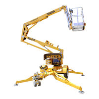
Haulotte Group HTA 13 P Operator's Maintenance Manual (142 pages)
Summit Series Trailer-Mounted Booms
Brand:
Haulotte Group
| Category:
Boom Lifts
| Size: 9 MB
Table of Contents
Table of Contents
3
1 Safety
7
Legend: Safety Advisories
7
Before Operation
8
During Operation
9
Table 1-1. Minimum Safe Approach Distances
9
Fall Protection
11
Manual Force
11
Wind Loading
12
Explosion Hazard
12
Table 1-2. Beaufort Scale
12
Maintenance
13
2 Specifications
15
Range of Motion
15
Figure 2-1. Range of Motion
15
Specifications
16
Warranty - New Product; Haulotte North America
18
Damaged Equipment Policy
20
3 Operation
21
Ground (Lower) Control Panel
22
Figure 3-1. Ground (Lower) Control Panel
22
Platform (Upper) Control Panel
25
Figure 3-2. Platform (Upper) Control Panel
25
Normal Operating Procedure
28
Figure 3-3. Boom Travel Latches
28
Figure 3-4. Outrigger Control Panel
29
Manual Boom Operation
31
Figure 3-5. Hand Pump Controls for Manual Operation
31
Figure 3-6. Location of Lift Cylinders for Manual Boom Lowering
32
Figure 3-7. Location of Manual Lowering Valves
32
Towing the Aerial Work Platform
33
Figure 3-8. Trailer Hitching
34
Lifting the Aerial Work Platform
35
Figure 3-9. Lifting the Aerial Work Platform
35
Transporting the Aerial Work Platform on a Truck Bed
36
Figure 3-10. Transport the Aerial Work Platform
36
4 Equipment Maintenance
37
Battery Recharge
38
Figure 4-1. Battery Charger Faceplate
38
Battery Fault Codes
39
Table 4-1. Battery Charger Fault Codes
39
Daily Service Checks
40
Figure 4-2. Outrigger Position Switch
41
Figure 4-3. Hydraulic Reservoir
42
Weekly Service Checks
43
Monthly Service Checks
44
Figure 4-4. Wheel Nut Tightening Sequence
44
Annual Service Checks
45
Figure 4-5. Display Run Time Hours
45
Figure 4-6. Machine Position for Slew Ring Measurement
46
Figure 4-7. Slew Ring Position Measurement
46
Figure 4-8. Platform Position after Rotation
46
Structural Inspection
47
Motor Drying Instructions
47
Leveling System Calibration Procedure
48
Figure 4-9. Position Machine for Leveling
48
Figure 4-10. Level Sensor Digitally Based
48
Figure 4-11. Level Sensor Pendulum Based
48
Figure 4-12. Ground (Lower) Control Panel for Leveling System
49
Overload Protection Calibration Procedure
50
Figure 4-13. Platform Position
50
Figure 4-14. Ground (Lower) Control Panel for Overload Protection
50
Additional Service Information
52
Manual Outrigger Retraction
53
Figure 4-16. Manual Outrigger Control Wire Harness
53
Figure 4-17. Bottom Side of the Ground (Lower) Control Box
53
Figure 4-18. Hydraulic Power Unit
53
Hydraulic Pressure Gauge
54
Figure 4-19. Attaching the Pressure Gauge to the Hydraulic Power Unit
54
Troubleshooting
55
Table 4-2. Trouble Shooting
55
Error Code Definitions - Controls
56
Table 4-3 Error Code Definitions
56
Error Codes
56
Error Code Definitions - Motor Controller
67
Table 4-4. Error Code Definitions - Motor Controller
67
Figure 4-15. Motor Controller
67
5 Cylinder Replacement
69
Master / Slave Cylinder Replacement
69
Figure 5-1. Location of Master Cylinder
69
Figure 5-2. Location of Slave Cylinder
70
Lift Cylinder Replacement
71
Figure 5-3. Location of Manual Lowering Valves
71
Figure 5-4. Push "Button" Lowering Valve
71
Figure 5-5. Lift Cylinder Replacement
71
Outrigger Cylinder Replacement
73
Figure 5-6. Outrigger Cylinder Replacement
73
Figure 5-7. Cylinder Valve Removal
73
6 Decal Replacement
75
Decal Kit - Ansi
76
Identification Plates & Optional Equipment - Ansi
78
Decals - Ansi
80
Decal Kit - Ce
84
Identification Plates & Optional Equipment - Ce
86
Decal Kit - Au
88
Identification Plates & Optional Equipment - Au
90
7 Optional Equipment
93
Drive and Set
94
Figure 7-1. Drive and Set Controls
94
Material Lift Hook
97
Figure 7-2. Disconnect Plug from Load Sense Module
97
Figure 7-3. Remove Platform (Upper) Control Box
97
Figure 7-4. Loopback Plug
97
Figure 7-5. Platform Removal
98
Figure 7-6. Material Lifting Hook Installation
98
Figure 7-7. Material Lift "Stowed" Position
99
Figure 7-8. Material Lift "In Use" Position
99
Platform Rotator
100
Figure 7-9. Manual Platform Rotator
100
8 Material Safety
101
Lead Acid Batteries, Wet, Filled with Acid - un 2794
101
Powerflow™ Aw Hvi Hydraulic Oil
106
9 Axle and Related Components
113
9A Dexter Axle and Related Components
113
Set up and Adjustment
113
Table 9-1. Wheel Torque Requirements
116
How to Use Your Electric Brakes Properly
117
Table 9-2. Trailer Wire Size Chart
117
Maintenance
118
Table 9-3. Maintenance Schedule
118
Table 9-4. Recommended Wheel Bearing Lubrication Specifications
124
Table 9-5. Tire Wear Diagnostic Chart
128
Table 9-6. Magnet Amperes Chart
129
Storage
130
Trouble Shooting
132
Table 9-7. Troubleshooting - Hydraulic Braking System
133
Table 9-8. Troubleshooting - Electric Braking System
135
9B Bradley Brake Adjustment
136
Aerial Work Platforms with Standard Brakes
136
Figure 9-1. Standard Brake Adjustment Procedure
137
Thirteen Percent (13 %) Grade Test
138
Aerial Work Platforms with Drive and Set Brakes
139
Figure 9-2. Drive & Set Brake Adjustment Procedure
139
Troubleshooting the Bradley Running Gear
140
Inspection Form for Haulotte Aerial Work Platforms
141
Advertisement
Advertisement
Related Products
Haulotte Group HTT 13
Haulotte Group HT21RT O
Haulotte Group HT61RT O
Haulotte Group HT61RT PRO
Haulotte Group HT23RTJ O
Haulotte Group HT67RTJ O
Haulotte Group HT23RTJ PRO
Haulotte Group HT23RTJ PRO SW
Haulotte Group HT67RTJ PRO
Haulotte Group HT21RT PRO SW
Haulotte Group Categories
Boom Lifts
Lifting Systems
Scissor Lifts
Utility Vehicle
Excavators
More Haulotte Group Manuals
Login
Sign In
OR
Sign in with Facebook
Sign in with Google
Upload manual
Upload from disk
Upload from URL