
GW Instek MDO-2000EG Manuals
Manuals and User Guides for GW Instek MDO-2000EG. We have 2 GW Instek MDO-2000EG manuals available for free PDF download: User Manual

GW Instek MDO-2000EG User Manual (377 pages)
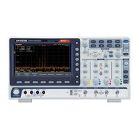
Mixed-Domain Oscilloscope
Brand: GW Instek
|
Category: Test Equipment
|
Size: 13 MB
Table of Contents
-
-
Appearance
16 -
Set up
30-
Tilt Stand30
-
Power up30
-
-
Easurement
40-
Measurement40
-
-
Gated Mode54
-
Statistics58
-
-
-
Acquisition
82 -
Display
99 -
Horizontal View
104 -
-
Bus Display120
-
Parallel Bus133
-
Bus Encoding135
-
-
Trigger
145 -
Search
185
-
Ogic Analyzer
199-
Logic Analyzer199
-
Overview200
-
Analog Waveform210
-
-
-
-
Overview216
-
Rear Panel216
-
Output Setup218
-
AM Modulation224
-
FM Modulation226
-
FSK Modulation228
-
Sweep230
-
-
Pectrum Analyzer
249-
-
Overview250
-
Display Overview251
-
Connections252
-
Configuration253
-
Measurement264
-
DMM267
-
DMM Function268
-
-
Power Supply277
-
-
Pplications
281-
Applications281
-
Introduction282
-
Overview282
-
-
DVM Application289
-
Mask Application295
-
-
-
Ave/Recall
305-
Save/Recall305
-
Save
315-
Save Image316
-
Save Waveform318
-
Save Setup320
-
Recall
323
-
-
Ile Utilities
331-
File Utilities331
-
File Navigation332
-
Create Folder333
-
Rename File334
-
Copy File to USB336
-
-
Hardcopy Key337
-
Maintenance353
-
Faq358
-
Appendix360
-
-
Model-Specific363
-
Common363
-
-
-
Gtp-070B-4370
-
Gtp-100B-4370
-
Gtp-200B-4371
-
-
Dimensions372
-
Index375
-
Advertisement
GW Instek MDO-2000EG User Manual (351 pages)
Mixed-Domain Oscilloscope
Brand: GW Instek
|
Category: Test Equipment
|
Size: 12 MB
Table of Contents
-
-
Appearance
16 -
Set up
29-
Tilt Stand29
-
Power up30
-
-
-
Easurement
40-
Measurement40
-
-
-
Gated Mode55
-
Statistics58
-
-
-
-
Acquisition
82 -
Display
99 -
Horizontal View
104 -
-
Bus Display120
-
Bus Encoding132
-
-
Trigger
142-
-
CAN Bus Trigger168
-
LIN Bus Trigger171
-
-
Search
174
-
-
-
Overview189
-
Rear Panel189
-
Output Setup191
-
AM Modulation197
-
FM Modulation199
-
FSK Modulation201
-
Sweep203
-
-
Pectrum Analyzer
222-
-
Overview223
-
Display Overview224
-
Connections226
-
Configuration226
-
Measurement238
-
-
DMM241
-
DMM Function242
-
Power Supply251
-
Pplications
255-
Applications255
-
Introduction256
-
Overview256
-
-
DVM Application263
-
Mask Application269
-
-
Ave/Recall
279-
Save/Recall279
-
Save
289-
-
Save Image290
-
Save Waveform292
-
Save Setup294
-
-
-
Recall
297
-
-
Ile Utilities
305-
File Utilities305
-
File Navigation306
-
Create Folder308
-
Rename File309
-
Copy File to USB311
-
Hardcopy Key312
-
Maintenance327
-
Faq333
-
Appendix335
-
-
Model-Specific338
-
Common339
-
-
-
Gtp-070B-4344
-
Gtp-100B-4344
-
Gtp-200B-4345
-
-
Dimensions346
-
Index349
-