Sign In
Upload
Manuals
Brands
GW Instek Manuals
Test Equipment
GDS-3652A
GW Instek GDS-3652A Manuals
Manuals and User Guides for GW Instek GDS-3652A. We have
2
GW Instek GDS-3652A manuals available for free PDF download: User Manual
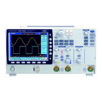
GW Instek GDS-3652A User Manual (417 pages)
Digital Storage Oscilloscope
Brand:
GW Instek
| Category:
Test Equipment
| Size: 20 MB
Table of Contents
Table of Contents
3
Safety Instructions
6
Safety Guidelines
7
Getting Started
11
GDS-3000A Series Overview
12
Integrated Instruments and Series Lineup
12
Main Features
12
Accessories
14
Appearance
16
Front Panel
16
GDS-3000A 2CH Models
16
GDS-3000A 4CH Models
16
Rear Panel and Right Side Panel
24
Calibration Output
24
LCD Display
26
Set up
28
Tilt Stand
28
Power up
28
First Time Use
29
How to Use this Manual
32
Built-In Help
37
Measurement
38
Basic Measurement
39
Channel Activation
39
Autoset
40
Run/Stop
41
Horizontal Position/Scale
42
Vertical Position/Scale
44
Automatic Measurement
45
Measurement Items
45
Add Measurement
49
Remove Measurement
51
Measurement Shortcuts
53
Gated Mode
55
Display All Mode
55
High Low Function
56
Statistics
58
Reference Levels
60
Cursor Measurement
61
Use Horizontal Cursors
61
Use Vertical Cursors
64
Math Operation
68
Basic Math Overview & Operators
68
Addition/Subtraction/Multiplication/Division
68
FFT Overview & Window Functions
70
FFT Operation
71
Advanced Math Overview
74
Advanced Math Operation
75
Advanced Configuration
79
Acquisition
82
Select Acquisition Mode
82
Show Waveform in XY Mode
83
Set the Record Length
86
Segmented Memory Acquisition
87
Segments Display
88
Set the Number of Segments
89
Run Segmented Memory
90
Navigate Segmented Memory
91
Play through each Segment
92
Measurement on Segments
93
Segment Info
96
Horizontal View
98
Move Waveform Position Horizontally
98
Select Horizontal Scale
99
Select Waveform Update Mode
99
Zoom Waveform Horizontally
101
Play/Pause
103
Vertical View (Channel)
106
Move Waveform Position Vertically
106
Select Vertical Scale
107
Select Coupling Mode
107
Input Impedance
108
Invert Waveform Vertically
108
Limit Bandwidth
109
Fine Scale
111
Expand by Ground/Center
112
Select Probe Type
113
Select Probe Attenuation Level
114
Set the Deskew
114
Bus Key Configuration
116
Bus Display
116
Serial Bus Overview
117
UART Serial Bus Configuration
119
I 2 C Serial Bus Interface
121
Serial Bus Interface
122
Parallel Bus
125
Input Configuration
125
Threshold Configuration
126
Bus Encoding
127
Parallel Bus Event Table
127
Adding a Label to the Parallel Bus
128
CAN Serial Bus Interface
130
LIN Serial Bus Interface
131
Bus Encoding
132
Threshold Configuration
133
Serial Bus Event Tables
134
Event Tables Format
136
Adding a Label to a Bus
137
Using Cursors with the Serial Bus
139
Trigger
141
Trigger Type Overview
141
Trigger: Types and Sources
143
Trigger Parameter Overview
143
Setup Holdoff Level
150
Setup Trigger Mode
151
Using the Edge Trigger
151
Using Advanced Delay Trigger
153
Using Pulse Width Trigger
154
Using Video Trigger
156
Pulse Runt Trigger
158
Using Rise and Fall Trigger
159
Using the Timeout Trigger
160
Using the Bus Trigger
162
UART BUS Trigger Settings
162
C Bus Trigger Settings
164
SPI Bus Trigger Settings
167
CAN Bus Trigger
168
LIN Bus Trigger
171
Parallel Bus Trigger
173
Using the Logic Trigger
174
Search
178
Configuring Search Events
178
Copying Search Event To/From Trigger Events
180
Search Event Navigation
180
Save Search Marks
181
Setting/Clearing Single Search Events
182
FFT Peak
182
System Settings
186
Select Menu Language
186
View System Information
186
Erase Memory
187
Erase Disk
187
Set Date and Time
188
Probe Compensation Frequency
189
QR Code Reader Function
189
Display
191
Display Waveform as Dots or Vectors
191
Ruler On/Off
191
Set the Intensity Level
192
Select Display Graticule
195
Freeze the Waveform (Run/Stop)
196
Turn off Menu
196
Arbitrary Wave Generator
197
Arbitrary Wave Generator Operation
198
Overview
198
Rear Panel
198
AWG Display Overview
199
Generator Connection
199
Output Setup
200
Select the Active Channel
200
Turn the Output on for the Selected Channel
201
Setting the Load Impedance
201
Setting the Phase
201
GEN1 and GEN2 Setup
202
Selecting a Waveform
202
Waveform Settings
203
AM Modulation
205
FM Modulation
208
FSK Modulation
210
Sweep
211
Manage Arbitrary Waveforms
213
Create New ARB Waveform
213
Edit an Existing ARB Waveform
215
Load ARB Waveform
222
Save ARB Waveform
223
Coupling and Tracking Waveforms Settings
225
Power Analysis (Optional)
229
Power Analysis Overview
231
Set the Deskew
231
Power Quality
233
Power Quality Parameter Overview
233
Using Power Quality Measurements
234
Switching Loss
237
Using Switching Loss Measurements
237
Harmonics
242
Harmonics Parameter Overview
242
Define Harmonic Inputs
243
Choosing a Harmonic Standard Test
244
Harmonics Setup - Default (None)
245
Harmonics Setup - IEC
246
Harmonics Display Options
248
Save Harmonic Measurements
250
Ripple
252
Using Ripple Measurements
252
Inrush
254
Using Inrush Current Measurements
254
Modulation
256
Using Modulation Measurements
256
Safe Operation Area
260
Using Safe Operation Area Measurements
260
Transient
264
Using Transient Measurements
264
Efficiency
267
Using Efficiency Measurements
267
B-H Curve
270
Using B-H Curve Measurements
270
Control Loop Response
274
Using Control Loop Response Measurements
274
Source
276
Setup Amplitude Profile
276
Setup AWG
278
Quit
280
Analysis Mode
280
Measure
280
Bode Plot
281
Overlay
283
File Utilities
284
Power Supply Rejection Ratio (PSRR)
286
Using PSRR Measurements
286
Source
289
Setup Amplitude Profile
289
Setup AWG
289
Quit
289
Analysis Mode
289
Measure
289
Bode Plot
289
Overlay
289
File Utilities
289
Turn On/Off
290
Using Turn On/Off Measurements
290
Spectrum Analyzer
294
Spectrum Analyzer Operation
295
Overview
295
Display Overview
295
Connections
297
Configuration
297
Selecting the Source
297
Setting the Trace Mode Options (Trace Type)
298
Setting the Detection Method
300
Configuring the Frequencies and Span
302
Configuring the Bandwidth
305
Configuring the Amplitude
306
Display
307
Measurement
310
Using the Search Function
310
Using the Cursors
311
Applications
313
Introduction
313
Overview
313
Running Applications
314
Go-Nogo Application
316
DVM Application
321
Data Log Application
323
Digital Filter Application
325
Mask Application
327
Select the Source Channel
327
Configure the Mask Violation
328
Auto Mask
329
User Defined Mask/ Create Mask
332
User-Defined Mask File Format
336
FRA Application
338
Connections
339
Launching the FRA Application
340
Setting Mode
340
FRA Run
341
Save/Recall
343
File Format/Utility
344
Image File Format
344
Waveform File Format
344
Spreadsheet File Format
345
Setup File Format
347
Create/Edit Labels
350
Save
353
File Type/Source/Destination
353
Save Image
354
Save Waveform
356
Save Setup
358
Recall
360
File Type/Source/Destination
360
Recall Default Panel Setting
360
Recall Waveform
362
Recall Setup
363
Reference Waveforms
365
Recall and Display Reference Waveforms
365
File Utilities
367
File Navigation
368
Create Folder
369
Rename File
370
Delete File or Folder
372
Copy File to USB
373
Hardcopy Key
375
Remote Control Config
377
Interface Configuration
378
Configure USB Interface
378
Configure the Ethernet Interface
379
Configure RS-232C Interface
382
Configure Socket Server
384
Socket Server Functionality Check
385
Web Server
390
Web Server Overview
390
Vertical Accuracy Calibration
395
Maintenance
395
Probe Compensation
397
Faq
399
The Probe Waveform Is Distorted
400
Appendix
401
Updating the Firmware
402
GDS-3000A Series Specifications
404
Model-Specific
404
Common
404
Probe Specifications
411
Model-Specific Probe Specifications
411
Common Probe Specifications
411
Dimensions
412
Certificate of Compliance
413
Index
415
Advertisement
GW Instek GDS-3652A User Manual (209 pages)
Digital Storage Oscilloscope
Brand:
GW Instek
| Category:
Test Equipment
| Size: 6 MB
Table of Contents
Table of Contents
3
Safety Instructions
5
Etting Started
10
GDS-3000 Series Overview
11
Getting Started
11
Series Lineup
11
Main Features
12
Accessories
13
Package Contents
16
Appearance
17
GDS-3502/3352/3252/3152 Front Panel
17
GDS-3504/3354/3254/3154 Front Panel
17
Rear Panel
23
Display
25
Set up
28
Tilt Stand
28
Power up
29
First Time Use
30
How to Use this Manual
32
Uick Reference
36
Quick Reference
36
Convention
38
Menu Tree / Operation Shortcuts
38
Acquire Key
39
Autoset Key
39
Auto-Range
40
CH1 ~ 4 Key
40
Cursor Key
41
Display Key
41
Help Key
41
Math Key
42
Measure Key
43
Print/Save Key
44
REF Key
44
Run/Stop Key
44
Save/Recall Key
45
Test Key
46
Test Key - Go-Nogo
46
Trigger Delay Menu
47
Trigger Edge Menu
47
Trigger Type Menu
47
Trigger Pulse Width Menu
48
Trigger Video Menu
48
Trigger Pulse Runt Menu
49
Trigger Rise & Fall Menu
49
Utility Key
50
Utility Key - I/O
50
Utility Key - File Utilities
51
Zoom Key
51
Default Settings
52
Built-In Help
54
Easurement
55
Measurement
55
Basic Measurement
57
Channel Activation
57
Autoset
58
Auto-Range
60
Run/Stop
62
Horizontal Position/Scale
63
Vertical Position/Scale
65
Split Window Mode
66
Automatic Measurement
68
Measurement Items
68
Individual Mode
71
Remove Measurement
72
Gated Mode
73
Display All Mode
74
Cursor Measurement
76
Use Horizontal Cursors
76
Use Vertical Cursors
79
Math Operation
82
Overview
82
Addition/Subtraction/Multiplication/Division
83
Fft
85
Applications
87
Overview
87
Running Applications
87
Uninstalling Applications
88
Using Go_Nogo
90
Power Analysis
95
Power Analysis Overview
95
Serial Bus
96
Onfiguration
98
Configuration
98
Acquisition
100
Select Acquisition Mode
100
Show Waveform in XY Mode
102
Set the Sampling Mode
104
Real Time Vs Equivalent Time Sampling Mode
105
Display
106
Display Waveform as Dots or Vectors
106
Set the Intensity Level
107
Set the Level of Persistence
107
Set the Waveform Intensity Type
109
Select Display Graticule
110
Freeze the Waveform (Run/Stop)
111
Turn off Menu
111
Horizontal View
112
Move Waveform Position Horizontally
112
Select Horizontal Scale
113
Select Waveform Update Mode
114
Zoom Waveform Horizontally
115
Move Waveform Position Vertically
117
Select Vertical Scale
117
Vertical View (Channel)
117
Select Coupling Mode
118
Invert Waveform Vertically
119
Set the Impedance
119
Limit Bandwidth
120
Expand by Ground/Center
121
Select Probe Type
122
Select Probe Attenuation Level
123
Set the Deskew
124
Trigger
125
Trigger Type Overview
125
Trigger Parameter Overview
127
Setup Holdoff Level
131
Setup Trigger Mode
132
Using the Edge Trigger
132
Using Advanced Delay Trigger
134
Using Pulse Width Trigger
135
Using Video Trigger
137
Pulse Runt Trigger
138
Using Rise and Fall Trigger
140
Select Menu Language
142
System Info / Language / Clock
142
View System Information
142
Erase Memory
143
Set Date and Time
144
Set the Buzzer Volume
144
Ave/Recall
146
Save/Recall
146
File Format/Utility
147
Image File Format
147
Waveform File Format
147
Spreadsheet File Format
148
Setup File Format
149
Create/Edit File Labels
151
File Type/Source/Destination
153
Save
153
Save Image
154
Save Image - Print/Save Key
155
Save Waveform
157
Save Setup
158
File Type/Source/Destination
160
Recall
160
Recall Default Panel Settings
160
Recall Waveform
162
Recall Setup
163
Recall and Display Reference Waveforms
165
Reference Waveforms
165
File Utilities
167
Print out
174
Emote Control Config
177
Remote Control Config
177
Configure USB Interface
178
Interface Configuration
178
Configure RS-232C Interface
179
Configure the Ethernet Interface
180
Configure GPIB Interface
183
USB/RS-232C Remote Control Software
184
Web Server
184
Web Server Overview
184
Aintenance
187
Maintenance
187
How to Use SPC Function
188
Vertical Accuracy Calibration
189
Probe Compensation
190
Activating Optional Software
192
Uninstalling Optional Software
192
Faq
194
Appendix
197
GDS-3000 Specifications
197
Probe Specifications
202
GDS-3000 Dimensions
204
Declaration of Conformity
205
Index
207
Advertisement
Related Products
GW Instek GDS-3654A
GW Instek GDS-3000 Series
GW Instek GDS-3152
GW Instek GDS-3352
GW Instek GDS-3502
GW Instek GDS-3254
GW Instek GDS-3354
GW Instek GDS-3504
GW Instek GDS-3554
GW Instek GDS-300 Series
GW Instek Categories
Power Supply
Test Equipment
Measuring Instruments
Multimeter
Inverter
More GW Instek Manuals
Login
Sign In
OR
Sign in with Facebook
Sign in with Google
Upload manual
Upload from disk
Upload from URL