Sign In
Upload
Manuals
Brands
Gree Manuals
Air Conditioner
GWH24QE-K6DNA1C/O
Gree GWH24QE-K6DNA1C/O Manuals
Manuals and User Guides for Gree GWH24QE-K6DNA1C/O. We have
5
Gree GWH24QE-K6DNA1C/O manuals available for free PDF download: Owner's Manual, Service Manual
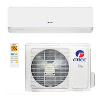
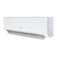
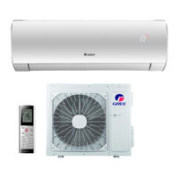
Gree GWH24QE-K6DNA1C/O Owner's Manual (208 pages)
Brand:
Gree
| Category:
Air Conditioner
| Size: 8 MB
Table of Contents
Table of Contents
3
Explanation of Symbols
4
The Refrigerant
5
Precautions
6
Parts Name
11
Buttons on Remote Controller
13
Introduction for Icons on Display Screen
13
Introduction for Buttons on Remote Controller
14
Function Introduction for Combination Buttons
18
Energy-Saving Function
18
Heating Function
19
Child Lock Function
19
I FEEL Function
19
Operation Guide
20
Replacement of Batteries in Remote Controller
20
Emergency Operation
21
Clean and Maintenance
21
Malfunction Analysis
24
General Phenomenon Analysis
24
Error Code
27
Safety Operation of Flammable Refrigerant
28
Installation Notes
28
Maintenance Notes
28
Installation Dimension Diagram
30
Safety Precautions for Installing and Relocating the Unit
31
Tools for Installation
32
Selection of Installation Location
32
Requirements for Electric Connection
33
Safety Precaution
33
Grounding Requirement
33
Installation of Indoor Unit
34
Check after Installation
39
Test Operation
39
Configuration of Connection Pipe
40
Pipe Expanding Method
42
Aire Acondicionado
44
Explicación de Símbolos
47
Refrigerante
48
Precauciones
49
Botones del Mando a Distancia
56
Presentación de Los Iconos en Pantalla
56
Introducción para Los Botones del Mando a Distancia
57
Introducción para la Combinación de Botones
62
Guía de Funcionamiento
63
Cambio de las Pilas del Mando a Distancia
63
Funcionamiento de Emergencia
64
Mantenimiento Limpieza y Mantenimiento
64
Mal Funcionamiento
67
Avisos de Instalación
71
Operación de Seguridad del Refrigerante Inflamable
71
Precauciones de Seguridad para Instalar y Reubicar la Unidad
74
Herramientas para la Instalación
75
Selección del Lugar de Instalación
75
Requisitos para la Conexión Eléctrica
76
Medidas de Seguridad
76
Instalación de la Unidad Interior
77
Verificare Después de la Instalación
82
Prueba de Funcionamineto
82
Método de Expansión de Tuberías
85
Explication des Symboles
91
Fluide Frigorigène
92
Précautions
93
Nom des Pièces
98
Touches de la Télécommande
100
Introduction aux ICônes Sur L'écran D'affichage
100
Introduction aux Touches de la Télécommande
101
Introduction aux Fonctions des Combinaisons de Touches
105
Manuel D'utilisation
107
Remplacement des Piles de la Télécommande
107
Fonctionnement D'urgence
108
Nettoyage et Maintenance
108
Nettoyer le Filtre
109
Code D'erreur
114
Utilisation Sécurisée de Fluide Frigorigène Inflammable
115
Schéma de Dimensions D'installation
117
Outils D'installation
119
Choix de L'emplacement D'installation
119
Consignes de Sécurité
120
Exigences de Mise à la Terre
120
Inspection après Installation
126
Test de Fonctionnement
126
Méthode de Prolongement du Tuyau
129
The Refrigerant
135
Precautions
136
Parts Name
141
Safety Operation of Flammable Refrigerant
142
Installation Dimension Diagram
144
Safety Precautions for Installing and Relocating the Unit
145
Tools for Installation
146
Selection of Installation Location
146
Requirements for Electric Connection
147
Installation of Outdoor Unit
148
Vacuum Pumping
151
Leakage Detection
151
Check after Installation
152
Test Operation
152
Configuration of Connection Pipe
153
Pipe Expanding Method
155
Explicación de Los Símbolos
160
Precauciones
162
Montaje
164
Manipulación Segura de Refrigerantes Inflamables
168
Notas sobre la Instalación
168
Diagrama de Dimensiones de Instalación
170
Advertencias de Seguridad para la Instalación y el Traslado de la Unidad
171
Selección del Lugar de Instalación
172
Requisitos de la Conexión Eléctrica
173
Advertencias de Seguridad
173
Instalación de la Unidad Exterior
174
Bombeo de Vacío
177
Detección de Fugas
177
Comprobaciones Posteriores a la Instalación
178
Marcha de Prueba
178
Configuración de la Tubería de Conexión
180
Método de Ensanchamiento de Tuberías
181
Fluide Frigorigène
187
Précautions
188
Nom des Pièces
193
Schéma de Dimensions D'installation
196
Outils D'installation
198
Choix de L'emplacement D'installation
198
Détection des Fuites
203
Inspection après Installation
204
Méthode de Prolongement du Tuyau
207
Advertisement
Gree GWH24QE-K6DNA1C/O Service Manual (122 pages)
Brand:
Gree
| Category:
Air Conditioner
| Size: 41 MB
Table of Contents
Table of Contents
2
Part Ⅰ : Technical Information
4
Model List
5
Specification Sheet
6
Capacity Curve in Different Outdoor Temperature
14
Cooling and Heating Data Sheet in Rated Frequency
14
Operation Characteristic Curve
14
Indoor Side Noise
15
Noise Curve
15
Outdoor Side Noise
15
1 Summary
4
3 Outline Dimension Diagram
16
Indoor Unit
16
Outdoor Unit
17
Gwh18Aad-K6Dna1B/O
18
Gwh24Qe-K6Dna1C/O
18
4 Refrigerant System Diagram
19
Connection Pipe Specification
19
5 Electrical Part
20
Wiring Diagram
20
Instruction
20
PCB Printed Diagram
23
Top View
23
Bottom View
23
6 Function and Control
26
Remote Controller Introduction
26
Buttons on Remote Controller
26
Icon Display on Remote Controller
26
ON/OFF Button
27
MODE Button
27
FAN Button
27
SWING Button
27
TURBO Button
28
I FEEL Button
28
Timer Button
28
Wifi Button
28
WIFI Function
29
Replacement of Batteries in Remote Controller
29
Emergency Operation
29
GREE+ App Operation Manual
30
Control Flow Chart
30
Operating Systems
30
Download and Installation
30
Ewpe Smart App Operation Manual
31
Brief Description of Modes and Functions
32
Basic Function of System
32
Other Control
32
Cooling Mode
32
Compulsory Defrosting Function
33
Refrigerant Recovery Function
33
Ambient Temperature Display Control Mode
33
Off-Peak Energization Function
33
Outdoor Units
34
Input Parameter Compensation and Calibration
34
Check Effective Judgment Controls of Parameters
34
Basic Functions
34
Special Functions
35
Defrosting Control
35
Control Logic
35
Compressor Control
35
Starting Estimation
36
Frequency Limited
36
Reducing Frequency at Normal Speed
36
Power Turn-Off
36
Voltage Sag Protection
38
Communication Fault
38
Module Protection
38
Module Overheating Protection
38
Starting-Up Failure Protection for Compressor
39
Out-Of-Step Protection for Compressor
39
Voltage Abnormity Protection for DC Bus
39
PFC Protection
39
Electric Heating Function of Chassis
40
Electric Heating Function of Compressor
40
Safety Precautions
41
Electrical Safety Precautions
41
Part Ⅱ : Installation and Maintenance
41
7 Notes for Installation and Maintenance
41
Safety Precautions for Installing and Relocating the Unit
42
Safety Precautions for Refrigerant
42
Installation Notes
43
Maintenance Notes
43
Qualification Requirement for Installation and Maintenance man
43
Safety Operation of Flammable Refrigerant
43
Main Tools for Installation and Maintenance
44
Installation Dimension Diagram
45
Installation Procedures
46
Start Installation
46
Electric Connection Requirement
47
Installation of Indoor Unit
47
Installation Parts-Checking
47
Selection of Installation Location
47
Connect the Pipe of Indoor Unit
48
Install Drain Hose
48
Install Wall-Mounting Frame
48
Outlet Pipe
48
Bind up Pipe
49
Connect Wire of Indoor Unit
49
Hang the Indoor Unit
49
Connect Indoor and Outdoor Pipes
50
Connect Outdoor Electric Wire
50
Fix the Support of Outdoor Unit
50
Installation of Outdoor Unit
50
Check after Installation and Test Operation
51
Leakage Detection
51
Preparation of Test Operation
51
Vacuum Pumping and Leak Detection
51
9 Maintenance
52
Malfunction Display of Indoor Unit
52
Error Code List
52
Discharging Method
53
Procedure of Troubleshooting
54
Malfunction of Temperature Sensor F1, F2
54
Main Detection Points
54
Malfunction Diagnosis Process
54
Malfunction of Blocked Protection of IDU Fan Motor H6
55
Malfunction of Protection of Jumper Cap C5
56
Communication Malfunction (E6)
58
Malfunction of Detecting Plate(WIFI) JF
59
Malfunction of Desynchronizing of Compressor (H7)
60
Malfunction of Temperature Sensor (F3/F4/F5)
62
Malfunction of Overload Protection of Compressor (H3)
63
Discharge High-Temperature Protection of Compressor (E4)
63
Charging Malfunction of Capacitor (PU)
64
Malfunction of Overload Protection (E8)
65
IPM Protection, Phase Current Overcurrent
66
Malfunction of Communication (E6)
67
Malfunction of Failure Start-Up of Compressor (LC)
68
Malfunction of Overcurrent Protection E5
69
Other Malfunction
70
Overheating Protection of IPM Module (P8)
70
DC Busbar Voltage Is too High (PH)
70
DC Busbar Voltage Is too Low (PL)
70
Maintenance Method for Normal Malfunction
71
Air Conditioner Cant be Started up
71
Poor Cooling (Heating) for Air Conditioner
71
Horizontal Louver Cant Swing
71
ODU Fan Motor Cant Operate
72
Compressor Cant Operate
72
Air Conditioner Is Leaking
72
Abnormal Sound and Vibration
72
10 Exploded View and Parts List
73
Indoor Unit
73
Outdoor Unit
83
Removal Procedure of Indoor Unit
91
Remove Filter
91
Remove Horizontal Louver
91
Remove Panel
92
Remove Electric Box Cover 2 and Detecting Plate
92
Remove Front Case Sub-Assy
92
Remove Electric Box Assy
93
Rotate the Electric Box Assy
93
Remove Evaporator Assy
94
Remove Motor and Cross Flow Blade
95
Remove Vertical Louver
95
Removal Procedure of Outdoor Unit
96
Remove Big Handle
96
Remove Top Panel
96
Remove Front Grille
96
Remove Cabinet
97
Remove Right Side Plate and Rear Grill
97
Remove Lef Side Plate
98
Remove Axial Flow Blade
98
Remove Motor
99
Remove Motor Support
99
Remove 4-Way Valve Assy
99
Remove Compressor
100
Remove Clapboard
100
Remove Valve Support Sub-Assy
100
Remove Condenser
101
Remove Grille , Panel and Rear Grill
102
Remove Left Side Plate and Right Side Plate
103
Remove Fan Motor
104
Remove Soundproof Sponge
105
Remove Condenser Sub-Assy
106
Before Disassembly
107
Remove Top Cover
107
Remove Grille
108
Remove Front Panel
108
Remove Right Side Plate
108
Remove Motor and Motor Support
109
Remove Isolation Sheet
109
Remove the Soundproof Sponge
114
Remove Isolation Plate
114
Set Temperature
116
Ambient Temperature
116
Appendix
116
Appendix 1: Reference Sheet of Celsius and Fahrenheit
116
Appendix 2: Configuration of Connection Pipe
116
Cut the Pip
117
Remove the Burrs
117
Appendix 3: Pipe Expanding Method
117
Resistance Table of Ambient Temperature Sensor for Indoor and Outdoor
118
Appendix 4: List of Resistance for Temperature Sensor
118
Resistance Table of Tube Temperature Sensors for Outdoor and Indoor
119
Resistance Table of Discharge Temperature Sensor for Outdoor (50K)
120
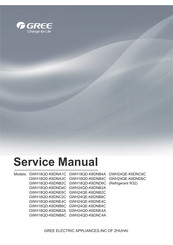
Gree GWH24QE-K6DNA1C/O Service Manual (131 pages)
Brand:
Gree
| Category:
Air Conditioner
| Size: 20 MB
Table of Contents
Table of Contents
2
Part : Technical Information
4
6Shfl¿Fdwlrqv 6Shfl¿Fdwlrq 6Khhw
7
2Shudwlrq &Kdudfwhulvwlf &Xuyh
15
Dsdflw\ 9Duldwlrq 5Dwlr $Ffruglqj Wr 7Hpshudwxuh
15
Rrolqj Dqg +Hdwlqj 'Dwd 6Khhw Lq 5Dwhg )Uhtxhqf
16
1Rlvh &Xuyh
17
1 Summary
4
3 Outline Dimension Diagram
18
Indoor Unit
18
2Xwgrru 8Qlw
19
4 Refrigerant System Diagram
20
5 Electrical Part
21
Wiring Diagram
21
PCB Printed Diagram
25
5Hprwh &Rqwuroohu ,Qwurgxfwlrq Ri <$1)
27
6 Function and Control
27
5Hprwh &Rqwuroohu ,Qwurgxfwlrq Ri <$1) :,)
31
5Hprwh &Rqwuroohu ,Qwurgxfwlrq Ri <$:)
36
5Hprwh &Rqwuroohu ,Qwurgxfwlrq Ri <$:) :L)L
40
Ulhi 'Hvfulswlrq Ri 0Rghv Dqg )Xqfwlrqv
44
Part : Installation and Maintenance
55
7 Notes for Installation and Maintenance
55
8 Installation
59
Installation Dimension Diagram
59
Qvwdoodwlrq 3DuwvFkhfnlqj
61
Selection of Installation Location
61
5Htxluhphqwv Iru Hohfwulf Frqqhfwlrq
61
Installation of Indoor Unit
61
QVWDOODWLRQ RI 2XWGRRU Unit
64
9Dfxxp 3Xpslqj Dqg /Hdn 'Hwhfwlrq
65
KHFN DIWHU ,QVWDOODWLRQ DQG 7HVW Operation
65
0Doixqfwlrq 'Lvsod\ Ri ,Qgrru 8Qlw
66
9 Maintenance
66
3Urfhgxuh Ri 7Urxeohvkrrwlqj
68
7Urxeohvkrrwlqj Iru 1Rupdo 0Doixqfwlrq
87
10 Exploded View and Parts List
89
Indoor Unit
89
2Xwgrru 8Qlw
103
5Hprydo 3Urfhgxuh Ri ,Qgrru 8Qlw
110
11 Removal Procedure
110
5Hprydo 3Urfhgxuh Ri 2Xwgrru 8Qlw
115
Appendix
126
Sshqgl
126
Appendix 3: Pipe Expanding MHWKRG
127
Appendix 4: List of RHVLVWDQFH IRU 7HPSHUDWXUH 6HQVRU
128
Advertisement
Gree GWH24QE-K6DNA1C/O Service Manual (118 pages)
Brand:
Gree
| Category:
Air Conditioner
| Size: 28 MB
Table of Contents
Table of Contents
2
1 Summary
4
Part : Technical Information
4
S Eci Cations
6
3 Outline Dimension Diagram
16
Indoor Unit
16
4 Refrigerant System Diagram
19
5 Electrical Part
20
6 Function and Control
26
7 Notes for Installation and Maintenance
41
Part : Installation and Maintenance
41
8 Installation
45
Selection of Installation Location
47
Installation of Indoor Unit
47
Detection
51
9 Maintenance
52
10 Exploded View and Parts List
74
Indoor Unit
74
11 Removal Procedure
88
Appendix
113
Appendix 3: Pipe Expanding M
114
Gree GWH24QE-K6DNA1C/O Owner's Manual (19 pages)
Brand:
Gree
| Category:
Air Conditioner
| Size: 13 MB
Table of Contents
Table of Contents
1
Safety Precautions
6
Parts Name
10
Installation Notice
11
Installation of Outdoor Unit
13
Test and Operation
15
Configuration of Connection Pipe
16
Advertisement
Related Products
Gree GWH24QE-K6DNB2C Series
Gree GWH24QE-K6DNB8C Series
Gree GWH24QE-K6DNE4C Series
Gree GWH24QE-K6DNB4C Series
Gree GWH24QE-K6DNC8C Series
Gree GWH24QE-K6DND6C Series
Gree GWH24QE-K6DNA1C/I
Gree GWH24QE-K6DNA3C/I
Gree GWH24QE-K6DNB6C/I
Gree GWH24QE-K6DNC2C/I
Gree Categories
Air Conditioner
Heat Pump
Dehumidifier
Controller
Air Handlers
More Gree Manuals
Login
Sign In
OR
Sign in with Facebook
Sign in with Google
Upload manual
Upload from disk
Upload from URL