Sign In
Upload
Manuals
Brands
GESTRA Manuals
Controller
NRR 2-61
GESTRA NRR 2-61 Manuals
Manuals and User Guides for GESTRA NRR 2-61. We have
2
GESTRA NRR 2-61 manuals available for free PDF download: Installation & Operating Manual, Original Installation & Operating Manual
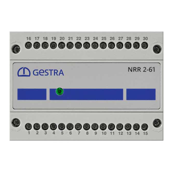
GESTRA NRR 2-61 Installation & Operating Manual (32 pages)
Level Controller
Brand:
GESTRA
| Category:
Controller
| Size: 0 MB
Table of Contents
Table of Contents
2
Content of this Manual
4
Scope of Delivery/Product Package
4
How to Use this Manual
5
Illustrations and Symbols Used
5
Hazard Symbols in this Manual
5
Types of Warning
6
Specialist Terms/Abbreviations
7
Usage for the Intended Purpose
8
Improper Use
9
Basic Safety Notes
10
Required Personnel Qualifications
10
Notes on Product Liability
10
Function
11
Possible Combinations of Functions and Equipment
11
Technical Data
12
Example Name Plate/Identification NRR 2-61
14
Factory Settings
15
Functional Elements and Dimensions
16
Installing the NRR 2-61 Level Controller
17
Electrical Connection Safety Notes
17
Wiring Diagram for NRR 2-61 Level Controller
18
Wiring Diagram for NRR 2-61 Level Controller as a 3C Controller
19
Electrical Connection
20
Bus Line, Cable Length and Cross-Section
20
Connecting the 24 V DC Power Supply
20
Connecting the Output Contacts
20
Notes on Connecting Inductive Loads
20
Connecting the Actual Value Output OUT1 and Analogue Output OUT2 (4-20 Ma)
20
Wiring Diagram of CAN Bus System
21
Example
21
Important Notes on Connecting the CAN Bus System
21
Changing the Equipment Settings
22
Configuring the Controller Group and Baud Rate
23
Setting the Measuring Range
24
Bringing into Service - Starting, Operation and Alarm
25
The MIN2/MAX2 Relays Are Configured as the MIN/MAX Alarm on the URB 60
25
Bringing into Service - Starting, Operation and Alarm
26
The MIN2/MAX2 Relays Are Configured as the Pump 1/2 Enable (ON/OFF) on the URB 60
26
Behaviour in the Event of a Malfunction
26
System Malfunctions
27
Causes
27
Before Starting Systematic Troubleshooting, Check the Installation and Configuration
27
Indication of System Malfunctions
28
What to Do in the Event of System Malfunctions
29
Taking out of Service
29
Disposal
29
Returning Decontaminated Equipment
29
Declaration of Conformity Standards and Directives
30
Advertisement
GESTRA NRR 2-61 Original Installation & Operating Manual (32 pages)
Level Controller
Brand:
GESTRA
| Category:
Controller
| Size: 0 MB
Table of Contents
Table of Contents
2
Content of this Manual
4
Scope of Delivery/Product Package
4
How to Use this Manual
5
Illustrations and Symbols Used
5
Hazard Symbols in this Manual
5
Types of Warning
6
Specialist Terms/Abbreviations
7
Usage for the Intended Purpose
8
Applicable Directives and Standards
9
Improper Use
9
Basic Safety Notes
10
Required Personnel Qualifications
10
Notes on Product Liability
10
Function
11
Possible Combinations of Functions and Equipment
11
Technical Data
12
Name Plate/Identification NRR 2-61
14
Factory Settings
15
Functional Elements and Dimensions
16
Installing the NRR 2-61 Level Controller
17
Electrical Connection Safety Notes
17
Wiring Diagram for NRR 2-61 Level Controller
18
Wiring Diagram for NRR 2-61 Level Controller as 3-Component Regulator
19
Electrical Connection
20
Bus Line, Cable Length and Cross-Section
20
Connecting the 24V DC Power Supply
20
Connecting Output Contacts
20
Notes on Connecting Inductive Loads
20
Connecting the Actual Value Output OUT1 and Analogue Output OUT2 (4 - 20 Ma)
20
Wiring Diagram of CAN Bus System
21
Example
21
Important Notes on Connecting the CAN Bus System
21
Changing the Equipment Settings
22
Configuring the Controller Group and Baud Rate
23
Setting the Measuring Range
24
Bringing into Service - Start, Operation and Alarm
25
The MIN2/MAX2 Relays Are Configured as the MIN/MAX Alarm on the URB 60
25
The MIN2/MAX2 Relays Are Configured as the Pump 1/2 Enable (ON/OFF) on the URB 60
26
Behaviour in the Event of a Malfunction
26
System Malfunctions
27
Causes
27
Check the Installation and Configuration before Systematic Troubleshooting
27
Indication of System Malfunctions
28
What to Do in the Event of System Malfunctions
29
Taking out of Service
29
Disposal
29
Returning Decontaminated Devices
29
EU Declaration of Conformity
30
Advertisement
Related Products
Gestra NRR 2-40
GESTRA NRR 2-50
GESTRA NRR 2-51
GESTRA NRR 2-52
GESTRA NRR 2-53
GESTRA NRR 2-60
GESTRA NRS 1-40
GESTRA NRS 1-9
GESTRA NRZ 2-1
GESTRA NRR 2-2e
GESTRA Categories
Switch
Controller
Control Unit
Measuring Instruments
Transmitter
More GESTRA Manuals
Login
Sign In
OR
Sign in with Facebook
Sign in with Google
Upload manual
Upload from disk
Upload from URL