Sign In
Upload
Manuals
Brands
GESTRA Manuals
Controller
LRR 1-52
GESTRA LRR 1-52 Manuals
Manuals and User Guides for GESTRA LRR 1-52. We have
3
GESTRA LRR 1-52 manuals available for free PDF download: Original Installation & Operating Manual, Installation & Operating Manual, Installation Instructions Manual
GESTRA LRR 1-52 Installation & Operating Manual (72 pages)
Conductivity Controller LRR Visual Display and Operating Unit URB
Brand:
GESTRA
| Category:
Controller
| Size: 3 MB
Table of Contents
Table of Contents
2
Content of this Manual
5
Scope of Delivery/Product Package
5
How to Use this Manual
6
Illustrations and Symbols Used
6
Hazard Symbols in this Manual
6
Types of Warning
7
Specialist Terms/Abbreviations
8
Usage for the Intended Purpose
10
IT Security and Rules for the Use of Ethernet Devices
11
Applicable Directives and Standards - LRR 1-52, LRR 1-53
11
Applicable Directives and Standards - URB 55
12
Improper Use
12
Basic Safety Notes
13
Required Personnel Qualifications
13
Notes on Product Liability
13
Function
14
Possible Combinations of Functions and Equipment
14
Technical Data - LRR 1-52, LRR 1-53
16
Technical Data - URB 55
18
Factory Settings - LRR 1-52, LRR 1-53
20
Lrr 1-52
20
Lrr 1-53
20
Lrr 1-52, Lrr 1-53
20
Factory Settings - URB 55
21
Name Plate / Marking - LRR 1-52, LRR 1-53
22
Name Plate / Marking - URB 55
23
Functional Elements and Dimensions - LRR 1-52, LRR 1-53
24
Installing the LRR 1-52, LRR 1-53 Conductivity Controller
25
Dimensions - URB 55
26
Required Installation Aperture in the Control Cabinet Door or Switch Panel
26
Installing the URB 55
27
Connecting the URB 55
28
Ports and Sockets on the Back of the Unit
28
Connection for 24 V DC Supply Voltage - Pin Assignment
28
Pin Assignment of the Data Line between the URB 55 and the LRR 1-52, LRR 1-53
28
Safety Notes for Electrical Connection
29
Wiring Diagram - LRR 1-52 Conductivity Controller
30
Connecting LRG 1X-XX Conductivity Electrodes
30
Connecting LRG 16-9 Conductivity Electrode
31
Wiring Diagram - LRR 1-53 Conductivity Controller
32
Connecting an LRGT 1X-X Conductivity Transmitter (4 - 20 Ma) with Earthing Point
32
Electrical Connection - LRR 1-52, LRR 1-53
33
Connecting the 24 V DC Power Supply
33
Connecting the MIN/MAX/CLOSED/OPEN Output Contacts
33
Notes on Connecting Inductive Loads
33
Connecting an LRG 16-9 Conductivity Electrode
33
Connecting an LRGT 1X-X Conductivity Transmitter
34
Connecting the Actual Value/Manipulated Variable Output (4 - 20 Ma)
34
Connecting the Standby Input (24 V DC)
34
Connecting the Potentiometer (0 - 1000 W)
34
Connecting the Data Line between the Conductivity Controller and the URB 55
35
Connecting the Spectormodul Bus System
35
Changing the Equipment Settings
36
Status Display on the LRR 1-52, LRR 1-53
38
Visual Display and Operating Unit URB 55
39
Switching on the Supply Voltage
39
Operation and Navigation
40
User Interface (Example)
40
Colour Coding of Input and Status Fields
40
Automatic Functions
41
Entering Parameters Using the Virtual Keypad
41
Parameter Input with Password Protection
42
Scroll Bar for Long Lists and Menus
42
Icons and Functions - LRR 1-52, LRR 1-53
43
The Home Screen of the LRR 1-52, LRR 1-53 Conductivity Controller
46
Alarms and Error Messages
47
Opening the Alarm History - Full List of All Alarms
48
System Settings
49
System Information
49
Setting the Date/Time
50
Password
50
Data Exchange Via Modbus TCP
51
Network Settings
51
VNC Server / Remote Software
52
Configuring the Conductivity Controller
53
Setting the MIN/MAX Switchpoints and Set Point
53
Trend Log
55
Test - Testing the Relays of the Connected Conductivity Controller
56
Continuous Blowdown Valve - Setting the Flushing Interval and Flushing Time
57
Continuous Blowdown Valve - Calibrating the Feedback Potentiometer for the Valve Position Display
58
Calibrating the Conductivity Electrode
59
Setting Correction Factor C
60
Setting the Measuring Range - LRR 1-52
61
Setting the Measuring Range - LRR 1-53
61
Setting the Control Parameters
62
Guide to Setting Control Parameters
62
Setting Automatic Intermittent Blowdown
63
System Malfunctions - URB 55
64
Display of System Malfunctions in the Alarm and Error List Using Fault Codes
64
Common Faults and Issues During Use of the URB 55
65
System Malfunctions - LRR 1-52, LRR 1-53
66
Causes
66
Before Starting Systematic Troubleshooting, Check the Installation and Configuration
66
What to Do in the Event of System Malfunctions
67
Checking Installation and Function
67
Taking the LRR 1-52, LRR 1-53 out of Service
67
Taking the URB 55 out of Service
67
Disposal
68
Returning Decontaminated Equipment
68
EU Declaration of Conformity - LRR 1-52, LRR 1-53
69
EU Declaration of Conformity - URB 55
69
Advertisement
GESTRA LRR 1-52 Original Installation & Operating Manual (72 pages)
Conductivity Controller LRR, Visual Display and Operating Unit URB
Brand:
GESTRA
| Category:
Controller
| Size: 3 MB
Table of Contents
Table of Contents
2
Content of this Manual
5
Scope of Supply, Product Package
5
How to Use this Manual
6
Illustrations and Symbols Used
6
Hazard Symbols in this Manual
6
Types of Warning
7
Specialist Terms, Abbreviations
8
Usage for the Intended Purpose
10
IT Security and Rules for the Use of Ethernet Devices
11
Applicable Standards for the LRR 1-52, LRR 1-53
11
Applicable Standards for the URB 55
12
Improper Use
12
Basic Safety Information
13
Required Personnel Qualifications
13
Notes on Product Liability
13
Function
14
Possible Combinations of Functions and Equipment
14
Technical Data for the LRR 1-52, LRR 1-53
16
Technical Data for the URB 55
18
Factory Settings of the LRR 1-52, LRR 1-53
20
Lrr 1-52
20
Lrr 1-53
20
Lrr 1-52, Lrr 1-53
20
Factory Default Settings of the URB 55
21
Rating Plate, Identification of the LRR 1-52, LRR 1-53
22
Rating Plate, Identification of the URB 55
23
Functional Elements and Dimensions of the LRR 1-52, LRR 1-53
24
Installing the LRR 1-52, LRR 1-53 Conductivity Controller
25
Dimensions of the URB 55
26
Required Installation Aperture in the Control Cabinet Door or Switch Panel
26
Installing the URB 55
27
Connecting the URB 55
28
Ports and Sockets on the Back of the Unit
28
Connection for 24 V DC Supply Voltage - Pin Assignment
28
Pin Assignment of Data Line between URB 55 and LRR 1-52, LRR 1-53
28
Safety Information on the Electrical Connection
29
Wiring Diagram for the LRR 1-52 Conductivity Controller
30
Connecting LRG 16-4 Conductivity Electrodes
30
Connecting an LRG 16-9 Conductivity Electrode
31
Wiring Diagram for the LRR 1-53 Conductivity Controller
32
Connecting an LRGT 1X-X Conductivity Transmitter (4 - 20 Ma)
32
Electrical Connection of the LRR 1-52, LRR 1-53
33
Connecting the 24 V DC Power Supply
33
Connecting the MIN/MAX/CLOSED/OPEN Output Contacts
33
Notes on Connecting Inductive Loads
33
Connecting an LRG 16-9 Conductivity Electrode
33
Connecting an LRGT 1X-X Conductivity Transmitter
34
Connecting the Actual Value/Manipulated Variable Output (4 - 20 Ma)
34
Connecting the Standby Input (24 V DC)
34
Connecting the Potentiometer (0 - 1000 W)
34
Connecting the Data Line between the Conductivity Controller and the URB 55
35
Connecting the Spectormodul Bus System
35
Changing the Equipment Settings
36
Status Display of the LRR 1-52, LRR 1-53
38
Visual Display and Operating Unit URB 55
39
Switching on the Supply Voltage
39
Operation and Navigation
40
User Interface (Example)
40
Color Coding of Input and Status Fields
40
Automatic Functions
41
Entering Parameters Using the Virtual Keypad
41
Entering Parameters with Password Protection
42
Scroll Bar for Long Lists and Menus
42
Icons and Functions of the LRR 1-52, LRR 1-53
43
Home Screen of LRR 1-52, LRR 1-53 Conductivity Controllers
46
Alarm and Fault Indications
47
Opening the Alarm History
48
System Settings
49
System Information
49
Setting the Date/Time
50
Password
50
Network Settings
51
Data Exchange Via Modbus TCP
51
VNC Server / Remote Software
52
Configuring the Conductivity Controller
53
Setting the MIN/MAX Switchpoints and Set Point
53
Trend Log
55
Test - Testing the Relays of the Connected Conductivity Controller
56
Setting the Flushing Interval and Flushing Time of the Continuous Blowdown Valve
57
Calibrating the Feedback Potentiometer for a Display of the Continuous Blowdown Valve Position
58
Calibrating the Conductivity Electrode
59
Setting Correction Factor C
60
Setting the Measuring Range of the LRR 1-52
61
Setting the Measuring Range of the LRR 1-53
61
Setting the Control Parameters
62
Guide to Setting Control Parameters
62
Setting Automatic Intermittent Blowdown
63
System Malfunctions of the URB 55
64
Indication of System Malfunctions in the Alarm and Error List Using Error Codes
64
Common Faults and Issues During Use of the URB 55
65
System Malfunctions of the LRR 1-52, LRR 1-53
66
Causes
66
Check the Installation and Configuration before Systematic Troubleshooting
66
What to Do in the Event of System Malfunctions
67
Check Installation and Function
67
Taking the LRR 1-52, LRR 1-53 out of Service
67
Taking out of Service URB 55
67
Disposal
68
Returning Decontaminated Equipment
68
UL Components
68
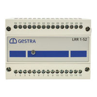
GESTRA LRR 1-52 Installation Instructions Manual (44 pages)
Conductivity Controller, Operating & Display Unit
Brand:
GESTRA
| Category:
Controller
| Size: 1 MB
Table of Contents
Table of Contents
2
Important Notes
5
Usage for the Intended Purpose
5
Glossary
5
Function
7
Safety Note
8
Directives and Standards
9
EU Pressure Equipment Directive 2014/68/EU
9
VdtüV Bulletin "Water Monitoring 100
9
LV (Low Voltage) Directive and EMC (Electromagnetic Compatibility)
9
ATEX (Atmosphère Explosible)
9
Ul/Cul (CSA) Approval
9
Note on the Declaration of Conformity / Declaration by the Manufacturer
9
Technical Data
10
Lrr 1-52, Lrr 1-53
10
Only LRR 1-52
11
Only LRR 1-53
11
Lrr 1-52, Lrr 1-53
11
Urb 50
12
Scope of Supply
12
Conductivity Controller LRR
12
Lrr
12
In Control Cabinet: Installing the Conductivity Controller
13
Dimensions LRR 1-52, LRR 1-53
13
Key
13
Installation in Control Cabinet
13
Name Plate / Marking
14
In Control Cabinet: Installing the Operating & Display Unit
15
Dimensions URB 50
15
Key
15
Installation in Control Cabinet
15
Name Plate / Marking
15
In Control Cabinet: Wiring the Conductivity Controller
16
Wiring Diagram for Conductivity Controller LRR 1-52
16
Wiring Diagram for Conductivity Controller LRR 1-53
17
Key
17
Transmitter LRGT 1
17
Valve
17
Actual Value Output 4-20 Ma
17
Contents - Continued
18
In Control Cabinet: Wiring the Operating & Display Unit
18
Back of Equipment, Position of Connector
18
Connection of Supply Voltage
18
Pin Assignment for Data Line LRR 1-52, LRR 1-53 - URB 50
18
Key
18
In Control Cabinet
19
Wiring the Conductivity Controller / the Operating & Display Unit
19
Connection of Supply Voltage
19
Connecting Output Contacts
19
Resistance Thermometer TRG 5
19
Connection of Conductivity Electrode LRG16-9
19
Connection of Conductivity Transmitter LRGT 1
20
Connection of Data Line for the Conductivity Controller / Operating & Display Unit
20
Connecting the Potentiometer (for Indication of Valve Positions), Connections in ../ out / 4-20 Ma
20
In the Plant
21
Wiring the Conductivity Electrode / Transmitter
21
Connecting Conductivity Electrode LRG 12-2, LRG 16-4, LRG 17-1 and LRG 19-1, Resistance Thermome- Ter TRG 5
21
Connection of Conductivity Electrode LRG16-9
21
Connection of Conductivity Transmitter LRGT 1
21
Conductivity Controller: Factory Settings
22
Conductivity Controller LRR 1-52, LRR 1-53
22
Conductivity Controller: Changing Factory Settings
23
Changing the Function and Unit
23
Tools
24
Operating & Display Unit URB 50
25
User Interface
25
Key
25
Switch on Supply Voltage
25
Explanation of Icons
26
Operating & Display Unit URB 50
26
Contents - Continued
29
Commissioning Procedure
29
Adjusting the MIN/MAX Switchpoints and Setpoint
29
Numberpad
29
Key
29
Conductivity Controller LRR 1-52: Setting the Measuring Range, Correction Factor and Temperature Compensation
30
Key
30
Conductivity Controller LRR 1-53: Setting Measuring Range
31
Setting the Control Parameters
32
Additional Information on Control Parameter Settings
32
Continuous Blowdown Valve: Setting the Purging Pulse and Duration
33
Continuous Blowdown Valve: Calibrating the Potentiometer for Indication of Valve Position
33
Key
33
Indication of Valve Position (Indicated in Percent and as Bar Graph)
33
Automatic Intermittent Blowdown
34
Operation
35
Manual Actuation of Continuous Blowdown Valve
35
Stand-By Operation
35
Key
35
Trending
36
Key
36
Testing MIN/MAX Alarm, Entering Date and Time
37
Setting up a Password and Logging in
38
Key
38
Setting up a Password and Logging in
39
Log out
39
Alarm List
40
Key
40
Error, Alarm and Warning Messages
41
Indication, Diagnosis and Remedy
41
Further Notes
42
Action against High Frequency Interference
42
Decommissioning / Replacing the Conductivity Controller LRR 1-5
42
Decommissioning / Replacing the Operating & Display Unit URB 50
42
Disposal
42
Advertisement
Advertisement
Related Products
GESTRA LRR 1-50
GESTRA LRR 1-51
GESTRA LRR 1-53
GESTRA LRR 1-60
GESTRA LRG 12-2
GESTRA LRG 17-1
GESTRA LRG 19-1
GESTRA LRGT 17-2
GESTRA LRR 1-40
Gestra LRGT 16-1
GESTRA Categories
Switch
Controller
Control Unit
Measuring Instruments
Transmitter
More GESTRA Manuals
Login
Sign In
OR
Sign in with Facebook
Sign in with Google
Upload manual
Upload from disk
Upload from URL