Sign In
Upload
Manuals
Brands
Georgii Kobold Manuals
Amplifier
KSV 6HE
Georgii Kobold KSV 6HE Manuals
Manuals and User Guides for Georgii Kobold KSV 6HE. We have
1
Georgii Kobold KSV 6HE manual available for free PDF download: Operating Instructions Manual
Georgii Kobold KSV 6HE Operating Instructions Manual (93 pages)
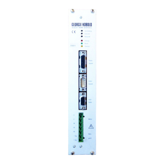
Servo Amplifier for Brushless Motors
Brand:
Georgii Kobold
| Category:
Amplifier
| Size: 0 MB
Table of Contents
Table of Contents
3
Chapter 1: General Information
9
Preliminary Remarks
9
About this Description
9
KSV 6HE Servo Drive Packages
9
Safety Instructions
11
Type of Instruction
11
Technical Staff
11
Use for the Intended Purpose
12
Protective Earthing
12
Hazard Warnings
13
CE Marking
13
Preconditions for Commissioning
14
Working with the Amplifier or the Power Supply
14
Chapter 2: Servo Amplifier
15
Technical Specifications
15
Type Code
15
Technical Specifications
16
Details
17
Design
17
Chassis
17
Fig. 1: Rack Mount Chassis 84 Units Wide
19
Connection: Assignment of Connectors and Details
20
Connector Assignments
20
Motor and Power Supply (Combicon Connector X1)
20
Control Signals "Steuersignale" (SUB-D Fem. Connector X2, 15-Pin)
20
Version Without Add-On Module
20
Version with Z1 Add-On Module
21
Version with Z2 Add-On Module
21
Version with Z4 Add-On Module
22
Position Sensor "Lagegeber" (SUB-D Female Connector X3, 9-Pin)
22
Encoder Signals "Gebersignale" (SUB-D Male Connector X4, 9-Pin)
23
Details about the Signals
23
Auxiliary Voltage Outputs
23
Setpoint through Differential Amplifier
23
Switching Inputs and Switching Outputs
24
Properties of the Switching Inputs and Outputs
24
Switching Input "Controller Enable
25
Switching Input "Reset Fault
25
Switching Output "Fault" or "Ready
26
Switching Output "Overload
26
Switching Output "Motor Standstill" or "Power Circuit Ready
27
Analog Outputs
28
Encoder Signals, Holding Function
28
Position Sensor
28
Motor Temperature Sensor
29
Sensor Fault Detection
29
Block Protection
29
Fault Memory
30
Interface Details
32
Connector X2, Control Signals, Switching Towards Zero
32
Fig. 2: Control Signals, Switching Towards Zero (Interface Details)
32
Connector X2, Control Signals, PLC-Compatible
33
Fig. 3: Control Signals, PLC-Compatible (Interface Details)
33
Connector X4, Encoder Signals, 5-Volt Version
34
Fig. 4: Encoder Signals, 5-Volt Version (Interface Details)
34
Connector X4, Encoder Signals, 24-Volt Version
35
Fig. 5: Encoder Signals, 24-Volt Version (Interface Details)
35
Connection Directions
36
Installation on the Mounting Plate
36
Fig. 6: Connection Directions
37
Fig. 7: Laying of the Motor Cables and Earthing of Their Shields
38
Installation in a 19" Rack System
39
Potential Equilization Cables
39
Mains Connection
40
Connection Mains - Mains Transformer
40
Connections Mains Transformer - RFI-Filter- Power Supply
41
Connection Power Supply - Servo Amplifier
41
Motor Connection, General Information
42
Motor Choke
43
Shield Connection of the External Shunt Resistor Cable
43
Connection, Shielding and Laying of the Control Leads
43
Setpoint Connection
44
Connection of the Encoder Signals
44
Connecting the Position Sensor (Resolver)
45
Connection of the Motor Temperature Sensor
46
Adjustment and Display Elements
47
Trim Potentiometers
47
Current Limiting and "Current" Rotary Switch
47
Leds
49
Modular Fittings and Expansions
50
Customer Module Kx
50
Add-On Modules Zx
50
Add-On Module Z1
51
Add-On Module Z2
52
Add-On Module Z4
53
Further Add-On Modules
55
Polarity Module Px
55
Encoder Modules G1 to G4
55
Pulse Setting
56
Index Pulse Adjustment
56
Function Module Fx
57
Hold Function F1
57
Field Weakening Mode F2
58
Option E1 External Supply of Control Circuit
59
Shutting down the Motor and Safety Shutdown
60
Shutting down Options
60
Estimating the Braking Distance
61
Emergency Stop and Safety Regulations
61
Commissioning
63
Precautions
63
Switching on for the First Time
63
Setting the Speed
64
Setting the Feedback: Normal Case
64
Fig. 8: Setpoint Potentiometer Connection for Commissioning
64
Setting the Feedback: Critical Applications
65
Setting the Feedback with Z4 Add-On Module
65
Setting the Current Limit
66
Setting the Offset
66
Setting the Holding Control Loop Amplification
67
Chapter 3: Power Supply and Accessories
68
Power Supply of the Servo Amplifiers
68
Load Factor
68
Power Supply
68
Design
68
Shunt Regulator
69
Connection Assignment (Terminal Blocks X5 and X6)
69
Leds
71
Technical Specifications of the Power Supply
71
External Shunt Resistor
71
Mains Transformers
72
General Information
72
Connections
73
Technical Specifications of the Mains Transformers
73
Accessories
75
Available Accessories and Order Numbers
75
Description of Accessories
75
Chassis
75
Connector Sets 099066020Z and 099066010Z
76
Motor Connection Cables 535246
76
Resolver/Encoder Connection Cable 535245
77
Ferrite Ring 042103010
78
Motor Chokes 038096010Z and 038097010Z
78
Fig. 9: Motor Chokes
79
RFI-Filters 002057020Z and 002057040Z
80
Shield Connection Plate 089159
80
Fig. 10: RFI-Filter
80
Chapter 4: Notes for Specialists
81
Modifications to the Servo Amplifier
81
Modifying the Controller Circuitry
81
Speed Control Range
81
Number of Motor Pole Pairs
82
Current Control Instead of Speed Control
83
Fig. 11: Location of the Jumpers on the Board
83
Changing the Direction of Rotation
84
Fig. 12: Location of the Jumpers on the Customer Module
84
Modifications to the Feedback
85
Reset Time
85
D Circuit
85
Modifications to the Z1, Z2, and Z4 Add-On Modules
85
Location of the Solder Bridges
85
Fig. 13: Solder Bridges on the Z1 Module
86
Fig. 14: Solder Bridges on the Z2 Module
86
Former Versions of Modules Z1 and Z2
87
Power Circuit Ready" Signal Instead of "Motor Standstill" Signal
87
Fig. 15: Solder Bridges on the Z4 Module
87
Switching off the Peak Current Rise
88
Switching off Active Braking at Controller Disable
88
Activating the Ramp Function
88
Adjusting and Limiting the I Component of the Speed Controller
88
Modifications to the Polarity Module
89
Ready" Signal Instead of "Fault" Signal
89
Fig. 16: Solder Bridges on the P1 and P2 Modules
89
Documentation of the Settings
90
Appendix
91
Appendix A EC Declaration of Conformity
91
Appendix B Terms of Warranty
92
Appendix C Table of Faults
92
Advertisement
Advertisement
Related Products
Georgii Kobold Categories
Amplifier
More Georgii Kobold Manuals
Login
Sign In
OR
Sign in with Facebook
Sign in with Google
Upload manual
Upload from disk
Upload from URL